Gas purifying device, gas purifying system and gas purifying method

a technology of gas purification device and purification system, which is applied in the direction of machine/engine, magnetic separation, separation process, etc., can solve the problems of high pressure loss of exhaust gas, difficult to efficiently remove pm, and increase load on exhaust gas generation sources such as engines, so as to achieve efficient removal of captured pm without heating

Inactive Publication Date: 2010-03-25
KK TOSHIBA
View PDF7 Cites 37 Cited by
  • Summary
  • Abstract
  • Description
  • Claims
  • Application Information

AI Technical Summary

Benefits of technology

[0009]Therefore, an object of the present invention is to provide a gas purifying device, a gas purifying system, and a gas purifying method capable of efficiently removing captured PM without heating to thereby purify a purification target gas.

Problems solved by technology

In this gas purifying device, mechanical dust collection is used for capturing the PM, and hence a pressure loss of the exhaust gas is high, which poses a problem of increasing load to the exhaust gas generation source such as an engine.
Particularly when the exhaust gas temperature is low (particularly at 200° C. or lower), it is difficult to remove the PM efficiently.
However, when an exhaust gas from an actual engine having sharp load fluctuation is treated using the conventional purification device, it is possible that the PM captured by the dielectric or discharge electrode is not burned completely and deposits thereon.
This may cause that the corona discharge becomes unstable, or that the corona discharge is no longer generated.
Moreover, the PM may deposit and reduce the cross-sectional area of the channel in which the exhaust gas flows, thereby causing a problem of increasing a pressure loss in the exhaust gas channel, or the like.

Method used


Image

  • Gas purifying device, gas purifying system and gas purifying method
  • Gas purifying device, gas purifying system and gas purifying method
  • Gas purifying device, gas purifying system and gas purifying method

Examples


first embodiment

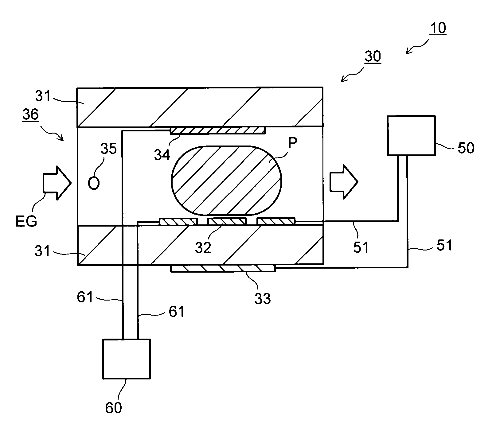
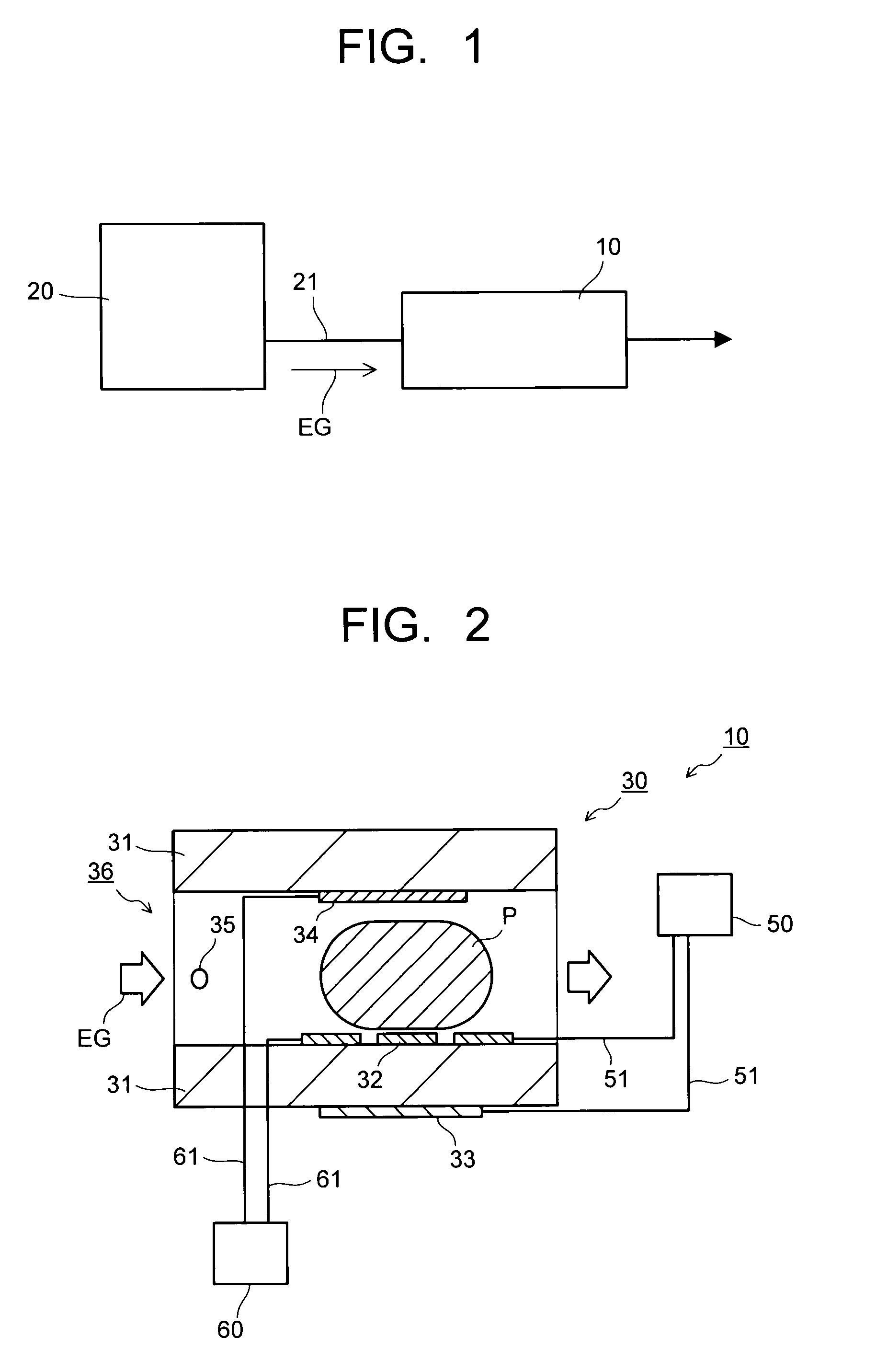
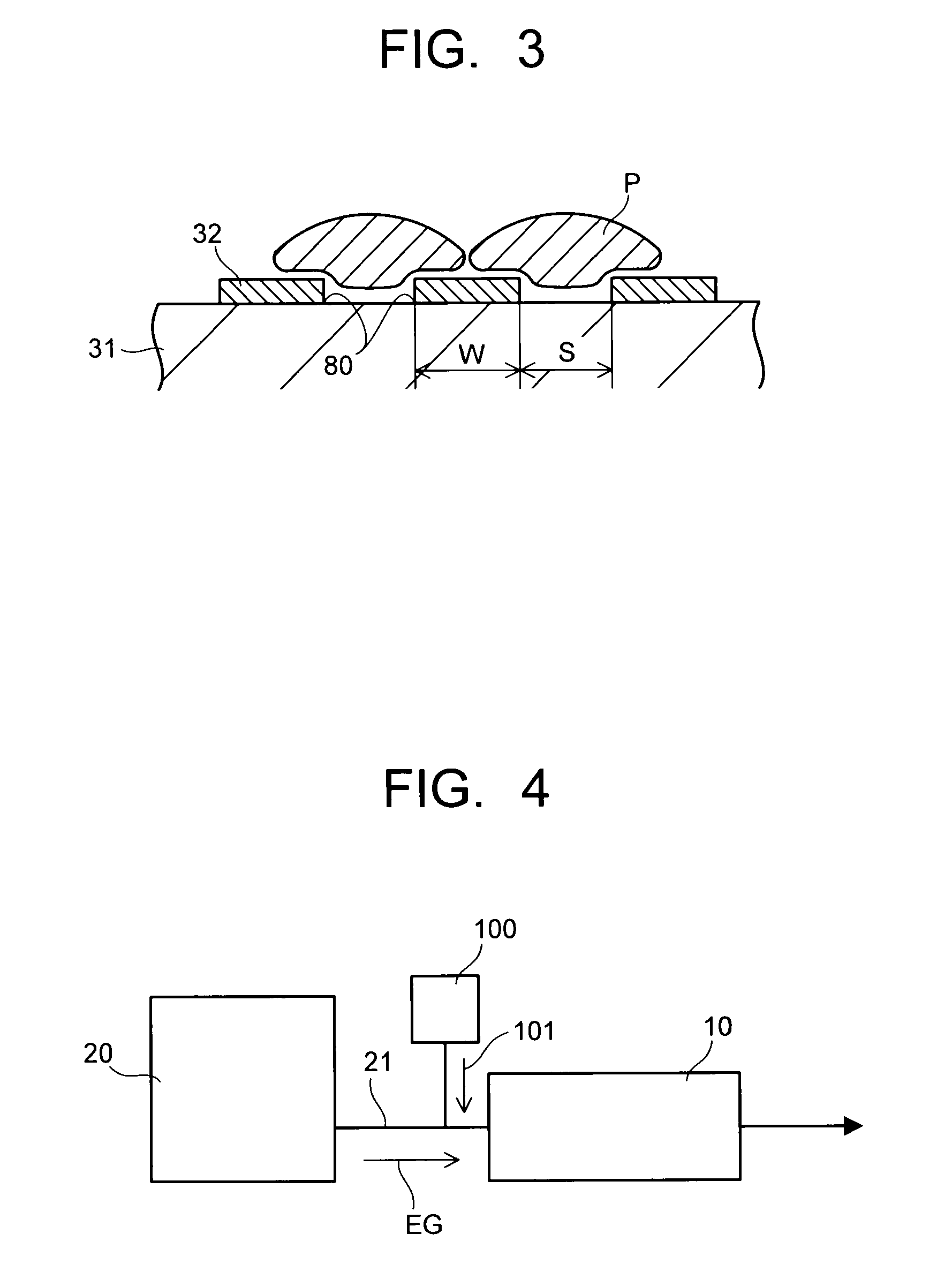
[0032]FIG. 1 is a block diagram schematically showing a gas purifying system including a gas purifying device 10 of a first embodiment according to the present invention. FIG. 2 is a view schematically showing a cross section of the gas purifying device 10 of the first embodiment according to the present invention. FIG. 3 is a view showing a cross section of a vicinity of discharge electrodes 32 for describing how a discharge plasma P is generated in the vicinity of the discharge electrodes 32.

[0033]As shown in FIG. 1, the gas purifying device 10 is provided in, for example, an exhaust channel 21 in which a purification target gas EG such as an exhaust gas emitted from the engine 20 of an automobile passes through. As shown in FIG. 2, this gas purifying device 10 includes a discharge reaction unit 30 provided in the channel of the purification target gas EG, a discharge power supply 50 connected to this discharge reaction unit 30 via a discharge electrical system 51, and a dust coll...

second embodiment

[0072]A gas purifying device 150 of a second embodiment according to the present invention has the same structure as the gas purifying device 10 of the first embodiment except that the charge electrode 35 in the gas purifying device 10 of the first embodiment is not provided, and shapes of the inner wall faces of the gas channel 36 on the sides where the discharge electrodes 32 and the dust collection counter electrode 34 are arranged are different. Thus mainly these different structures will be described here.

[0073]FIG. 5 is a view schematically showing a cross section of the gas purifying device 150 of the second embodiment according to the present invention. Note that the same parts as those in the structure of the gas purifying device 10 of the first embodiment are given the same reference numerals, and overlapping descriptions are omitted or simplified.

[0074]As shown in FIG. 5, the gas purifying device 150 of the second embodiment includes a discharge reaction unit 30 provided ...

third embodiment

[0086]A gas purifying device 200 of a third embodiment according to the present invention has the same structure as the gas purifying device 10 of the first embodiment except that that the charge electrode 35 in the gas purifying device 10 of the first embodiment is not provided, and catalyst layers 201, 202 are provided on the inner wall faces of the gas channel 36 on the sides where the discharge electrodes 32 and the dust collection counter electrode 34 are arranged. Thus mainly these different structures will be described here.

[0087]FIG. 6 is a view schematically showing a cross section of the gas purifying device 200 of the third embodiment according to the present invention. Note that the same parts as those in the structure of the gas purifying device 10 of the first embodiment are given the same reference numerals, and overlapping descriptions are omitted or simplified.

[0088]As shown in FIG. 6, the gas purifying device 200 of the third embodiment includes a discharge reactio...


PUM

PropertyMeasurementUnit
temperatureaaaaaaaaaa
exhaust gas temperatureaaaaaaaaaa
thicknessaaaaaaaaaa

Abstract

A gas purifying device (10) includes a first electric field forming unit which forms an electric field for discharge in a gas channel (36) in which a purification target gas (EG) flows to generate a discharge plasma (P), and charges and burns PM included in the purification target gas (EG) by action of the discharge plasma (P), a second electric field forming unit which forms an electric field for dust collection to capture the charged PM by an electrical dust collection function and draw out the discharge plasma (P) to the gas channel side, and a charge electrode (35) for charging a flowing purification target gas (EG), which is disposed on an upstream side positions where the first electric field forming unit and the second electric field forming unit are disposed.

Description

TECHNICAL FIELD [0001]The present invention relates to a gas purifying device, a gas purifying system and a gas purifying method for purifying a purification target gas including hazardous substances such as particulate matter by removing the hazardous substances therefrom.BACKGROUND ART [0002]Conventionally, as gas purifying devices for purifying hazardous substances such as particulate matter (PM) from an exhaust gas emitted from an exhaust gas generation source such as an engine, there are devices in which a PM filter is provided in a gas channel of an exhaust gas including PM, and the PM is captured by the PM filter. For example, the description of JP-A 11-062558 (KOKAI) discloses a gas purifying device in which substances such as carbon included in the PM captured by the PM filter are burned and removed by a heater, so as to restore the function of the PM filter.[0003]In this gas purifying device, mechanical dust collection is used for capturing the PM, and hence a pressure los...

Claims


Application Information

Patent Timeline
Patent Type & Authority Applications(United States)
IPC IPC(8): B03C3/34F01N3/02B01D53/94B03C3/02B03C3/08B03C3/38B03C3/40B03C3/41F01N3/24
CPCB01D53/32F01N13/011B01D2255/102B01D2255/40B01D2255/908B01D2258/01B01D2259/818B03C3/08B03C3/12B03C3/47B03C2201/30F01N3/0275F01N3/035F01N2240/28F01N13/017F01N13/009B01D53/922B03C3/025B03C3/60B03C2201/12B03C3/366B03C3/017B03C3/66B03C3/68B03C2201/24
Inventor TANAKA, MOTOFUMIYASUI, HIROYUKI
Owner KK TOSHIBA
Why Eureka
Try Eureka