Insulated beverage container

Inactive Publication Date: 2010-03-25
JOHNSON MATTHEW J +1
View PDF22 Cites 71 Cited by
  • Summary
  • Abstract
  • Description
  • Claims
  • Application Information

AI Technical Summary

Benefits of technology

[0011]The insulated beverage container is a container, such as a coffee cup, providing thermal insulation for the user's hand. The insulated beverage container includes an annular wall having an upper end and a lower end, with the annular wall being elongated along a vertical direction. A base is secured to the lower end of the annular wall so that an upper surface of the base and the annular wall define an open interior region therein adapted for receiving and containing fluids. The annular wall and base may be formed in a conventional manner to form a beverage cup.
[0012]Further, a plurality of tubes are formed on an outer surface of the annular wall. Each tube is hollow and defines an air passage therein, with the air contained therein acting as a heat exchanger. Each tube is elongated along the vertical direction and has upper and lower air flow apertures formed therethrough. The air flow apertures may have any desired size, contour or configuration, dependent upon the desired air flow characteristic

Problems solved by technology

However, EPS cups are generally considered to be environmentally unfriendly due to the fact that EPS is not biodegradable.
Additionally, in order to print EPS cups, a slow and relatively costly off-line printing process must be used because the cups must be printed after they have been formed, and their relatively rough surface does not permit high-resolution printing.
Conventional single-wall paper containers are generally considered to be more environmentally friendly than EPS cups, but they often have poor thermal insulating properties.
This process, however, is both expensive and wasteful.
This process requires additional labor and slows the speed of service.
Further, the need for cups and sleeves requires additional and simultaneous purchasing, additional storage space, and additional inventory management.
Cup sleeves further have a tendency to fall off of the cups, do not conveniently fit in all vehicle cup holders, and further cover the graphics printed on the cup.
Although thermally insulated and strong, such cups are expensive to manufacture because the corrugated or embossed sheet must be

Method used


Image

  • Insulated beverage container
  • Insulated beverage container
  • Insulated beverage container

Examples


Example

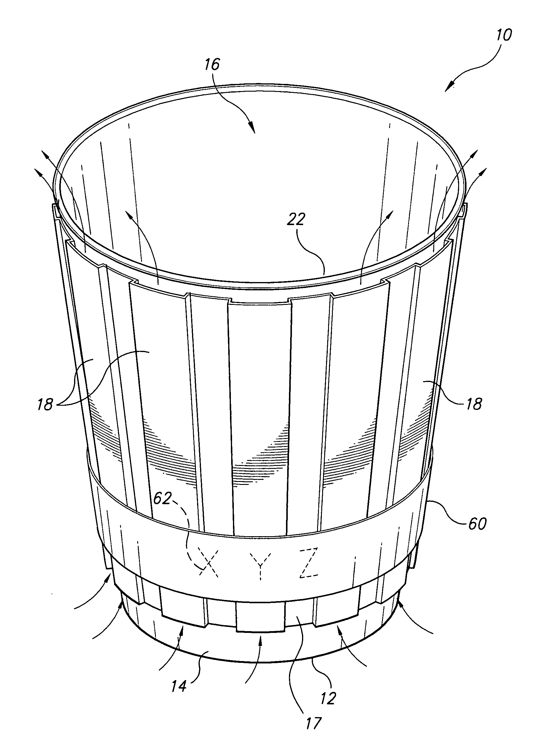
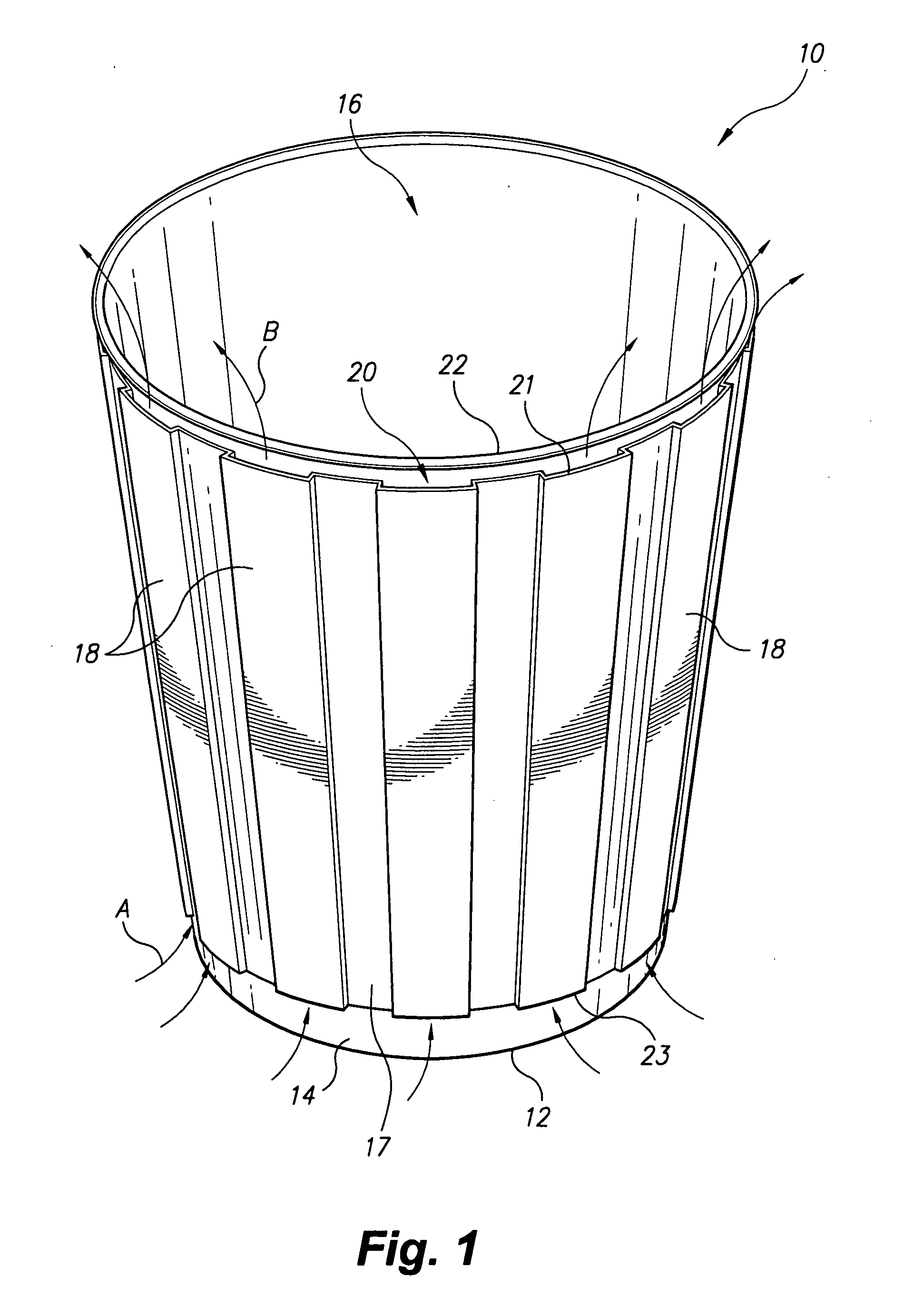
[0025]FIG. 1 shows a first embodiment of an insulated beverage container 10, such as a coffee cup, that provides thermal insulation for the user's hand. As shown in FIG. 1, the insulated beverage container 10 includes an annular wall 14 having an upper end and a lower end, with the annular wall 14 being elongated along a vertical direction. The upper end may have an annular lip or rim 22 formed thereon that allows for releasable attachment of a lid, as is conventionally known.

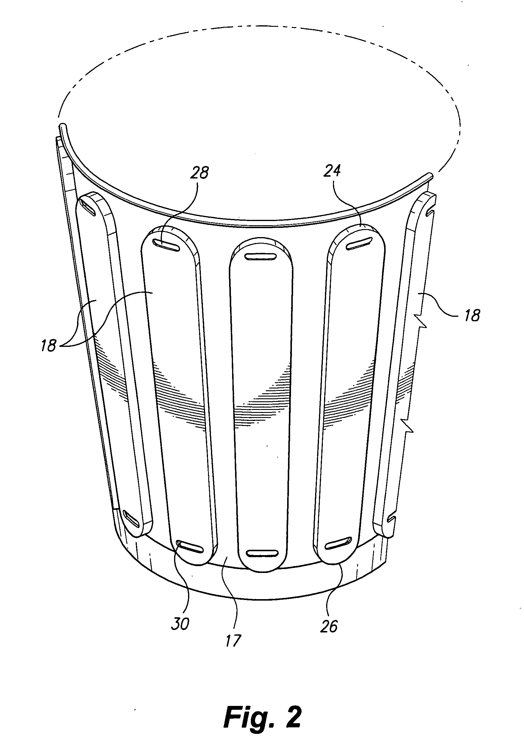
[0026]A base 12 is secured to the lower end of the annular wall 14 so that an upper surface of the base 12 and the annular wall 14 define an open interior region 16 therein adapted for receiving and containing fluids. The annular wall 14 and base 12 may be formed in any conventional manner to form a beverage receiving cup, as is conventionally known. It should be understood that the container 10 illustrated in FIG. 1 is shown for exemplary purposes only, and that the outer layer, to be described in greater deta...


PUM


Abstract

The insulated beverage container is a container, such as a coffee cup, providing thermal insulation for the user's hand. The container includes a vertically extending annular wall and a base, forming a beverage-receiving cup. A plurality of tubes are secured to an outer surface of the annular wall. Each tube is hollow and defines an air passage therein, and is further elongated along the vertical direction, having upper and lower air flow apertures formed therethrough. In use, heat generated by the beverage heats the air contained within the tubes. As the air rises within the tubes, ambient air at a lower temperature is drawn through the lower air flow apertures and the heated air is expelled through the upper air flow apertures, maintaining a flow of cooled air from the environment through the tubes.

Description

CROSS-REFERENCE TO RELATED APPLICATION[0001]This application claims the benefit of U.S. Provisional Patent Application Ser. No. 61 / 136,648, filed Sep. 23, 2008.BACKGROUND OF THE INVENTION[0002]1. Field of the Invention[0003]The present invention relates to cups, and particularly to an insulated beverage container, such as a coffee cup, tea cup, or the like.[0004]2. Description of the Related Art[0005]Beverage containers, such as cups for coffee, tea, hot chocolate, soup and the like, are typically formed from expanded polystyrene (EPS) or similar materials. EPS is an efficient thermal insulator for maintaining the beverage at a desired temperature for an extended period of time. Such cups further provide a thermal barrier between the hot or cold temperature of the beverage and the user's hand. However, EPS cups are generally considered to be environmentally unfriendly due to the fact that EPS is not biodegradable. As a result, their use has been banned in some municipalities.[0006]A...

Claims


Application Information

Patent Timeline
IPC IPC(8): B65D81/38
CPCB65D25/20B65D2203/00B65D81/3876B65D81/3869
Inventor JOHNSON, MATTHEW J.JOHNSON, ANDREW
Owner JOHNSON MATTHEW J
Why Eureka
Try Eureka