

Vibrator for ultrasonic motor
- Summary
- Abstract
- Description
- Claims
- Application Information
AI Technical Summary
Benefits of technology
Problems solved by technology
Method used
Image

Examples
example 1
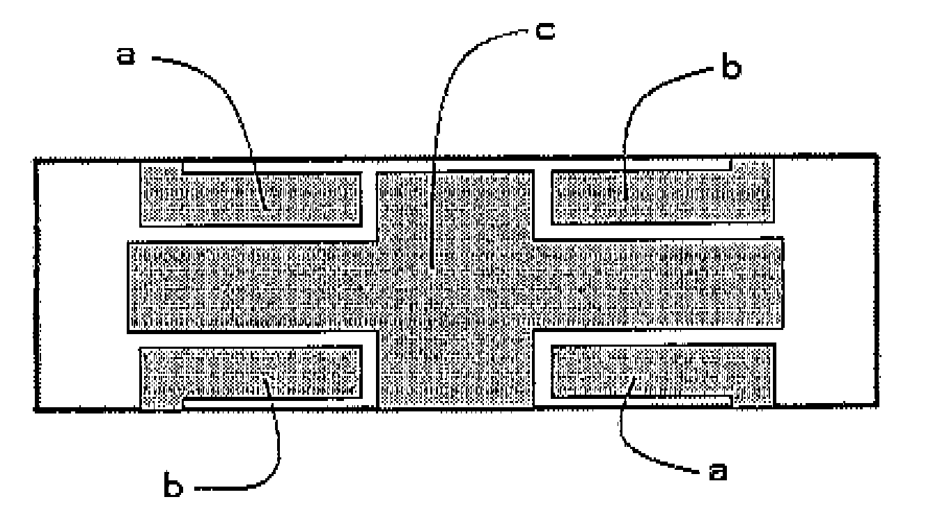
[0049]A rectangular piezoelectric element plate of 2 mm in thickness×30 mm in length×8.4 mm in width was prepared. The electrode regions for exciting first stretching vibration and for exciting second flexural vibration were provided according to the shapes and arrangement according to FIG. 1. The electrode for exciting first stretching vibration was a cross shape of length 20 mm, which occupied 41% of the piezoelectric element area. Each of the electrodes for exciting second flexural vibration had length of 6 mm and width of 1.5 mm and the two pairs of electrodes occupied 14% of the piezoelectric element area. On the center of the short side, a stator was attached.
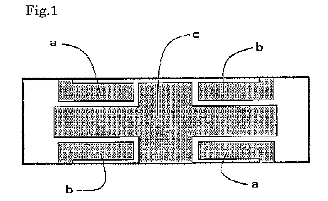
[0050]The results of measurements on vibration states of a stator attached to the end of piezoelectric vibrator are shown in FIG. 16. In the phase difference of 180 degrees, 100Vp-p−55.2 KHz alternate voltage was applied to electrodes a and b. At the same time, to electrode c, alternate voltage of 100Vp-p with the same fr...
example 2
[0051]A rectangular piezoelectric element plate of 2 mm in thickness×30 mm in length×8.4 mm in width was prepared. The electrode regions for exciting first stretching vibration and for exciting second flexural vibration were provided according to the shapes and arrangement according to FIG. 8. The electrode for first stretching vibration was a 6 mm-long rectangle which occupied 19% of the piezoelectric element area. Each of the electrodes for second flexural vibration was 6 mm long and 1.5 mm wide and the two pairs of the electrodes occupied 14% of the piezoelectric element area. In the same manner as in Example 1, on the center of the short side, a stator was attached.
[0052]Voltage was applied to each of the electrodes in the same manner as in Example 1, and differences in measurement results from Example 1 are mainly described below. In the measurement results, a significant decrease in amplitude of first stretching vibration due to reduction in the polarized region size to 20% of...
example 3
[0053]A rectangular piezoelectric element plate of 2 mm in thickness×30 mm in length×8.4 mm in width was prepared. The electrode regions for exciting first stretching vibration and for exciting second flexural vibration were provided according to the shapes and arrangement according to FIG. 9. The electrode for first stretching vibration was a 20 mm-long rectangle which occupied 29% of the piezoelectric element area. Each of the electrodes for second flexural vibration was 6 mm long and 1.5 mm wide and the two pairs of the electrodes occupied 14% of the piezoelectric element area, as in Example 1. In the same manner as in Example 1, on the center of the short side, a stator was attached.
[0054]Voltage was applied to each of the electrodes in the same manner as in Example 1, and differences in measurement results from Examples 1 and 2 are mainly described below. In the measurement results, it was observed that the amplitude of first stretching vibration became a little smaller than th...
PUM
 Abstract
Description
Claims
Application Information