
Eureka
For R&D, Eureka makes reading and utilizing patents & technical documents easy.
Eureka AIR
Designed for self-driven R&D workflows. Generate viable solutions, solve complex R&D challenges, empower your innovation with AI.

Eureka Materials
Designed for material experts only. Revolutionize your material R&D, from search, analyze, to developing new materials.

TechResearch
Generate reliable direction feasibility study reports for your R&D in just a few steps.

TechSeek
Discover and master advanced knowledge NOW. Basics, ideas, possibilities, all at once.

TechMind
As an expert in R&D Theories, TechMind can generates customized viable solutions instantly.

TechRisk
Analyze your overall solution with one click, know your potential R&D risks in advance.

TechMonitor
Get weekly tech updates, stay abreast of the latest tech innovations and key insights.
Antenna Arrangement and Antenna Housing
- Summary
- Abstract
- Description
- Claims
- Application Information
AI Technical Summary
Benefits of technology
Problems solved by technology
Method used
Image

Examples
Embodiment Construction
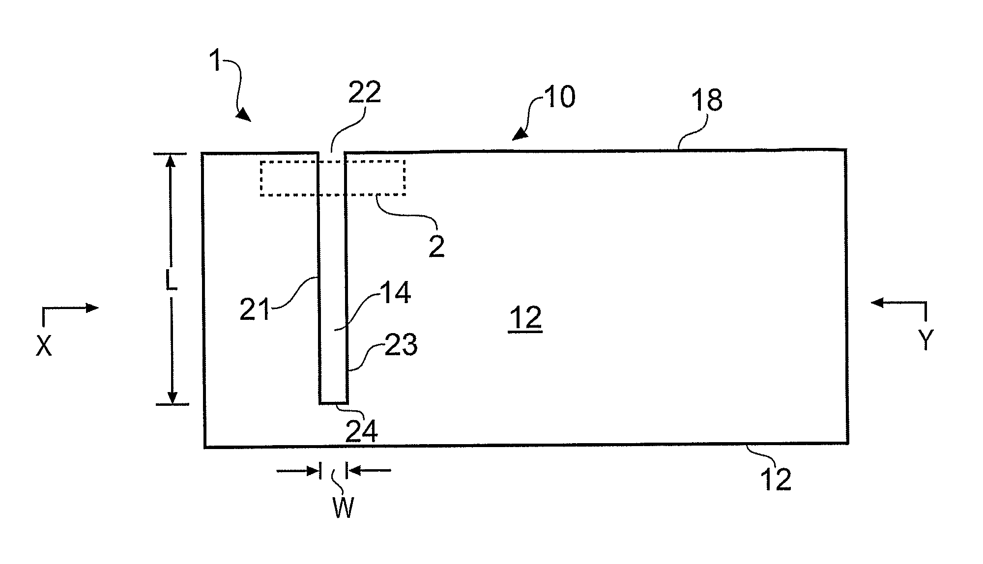
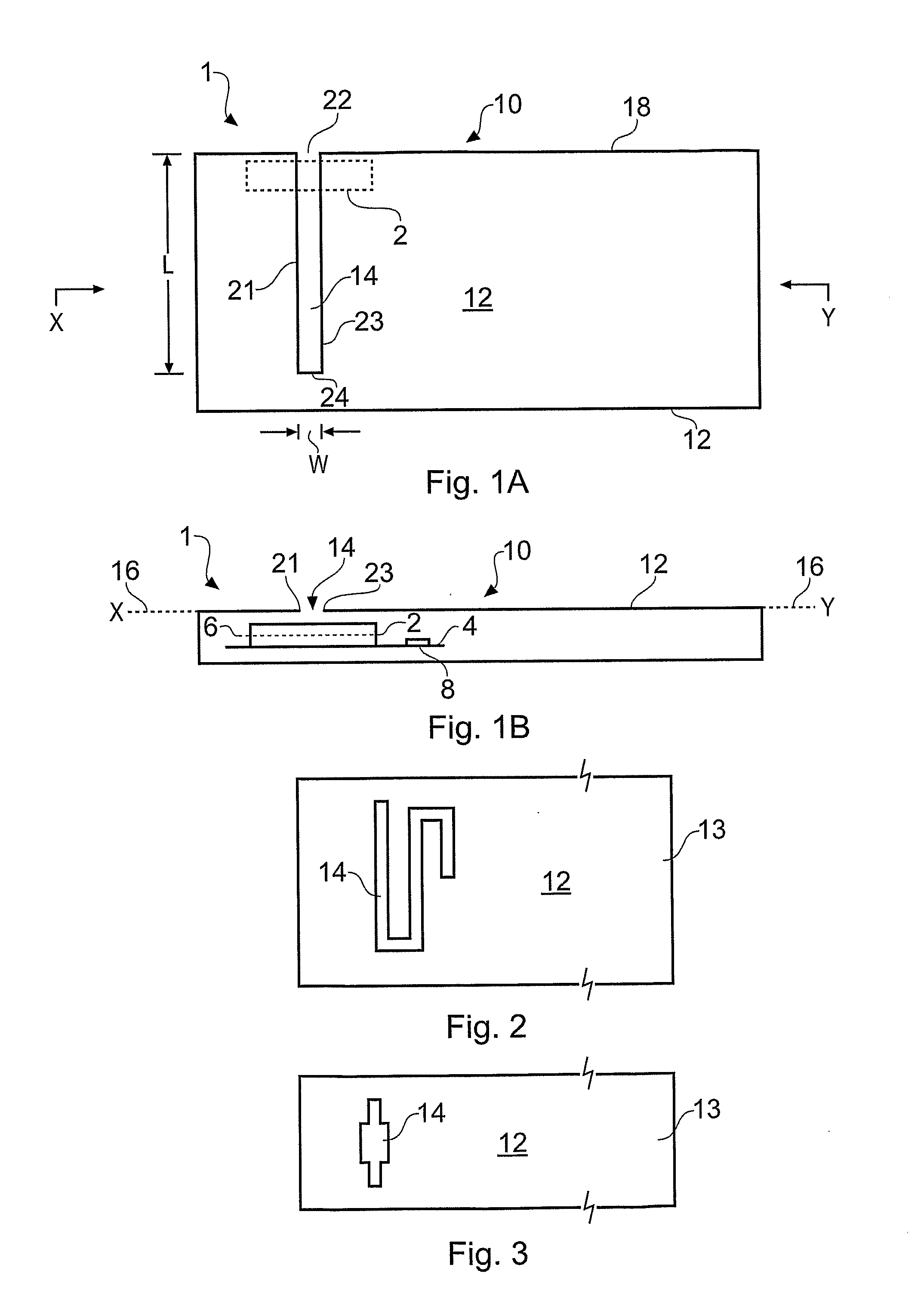
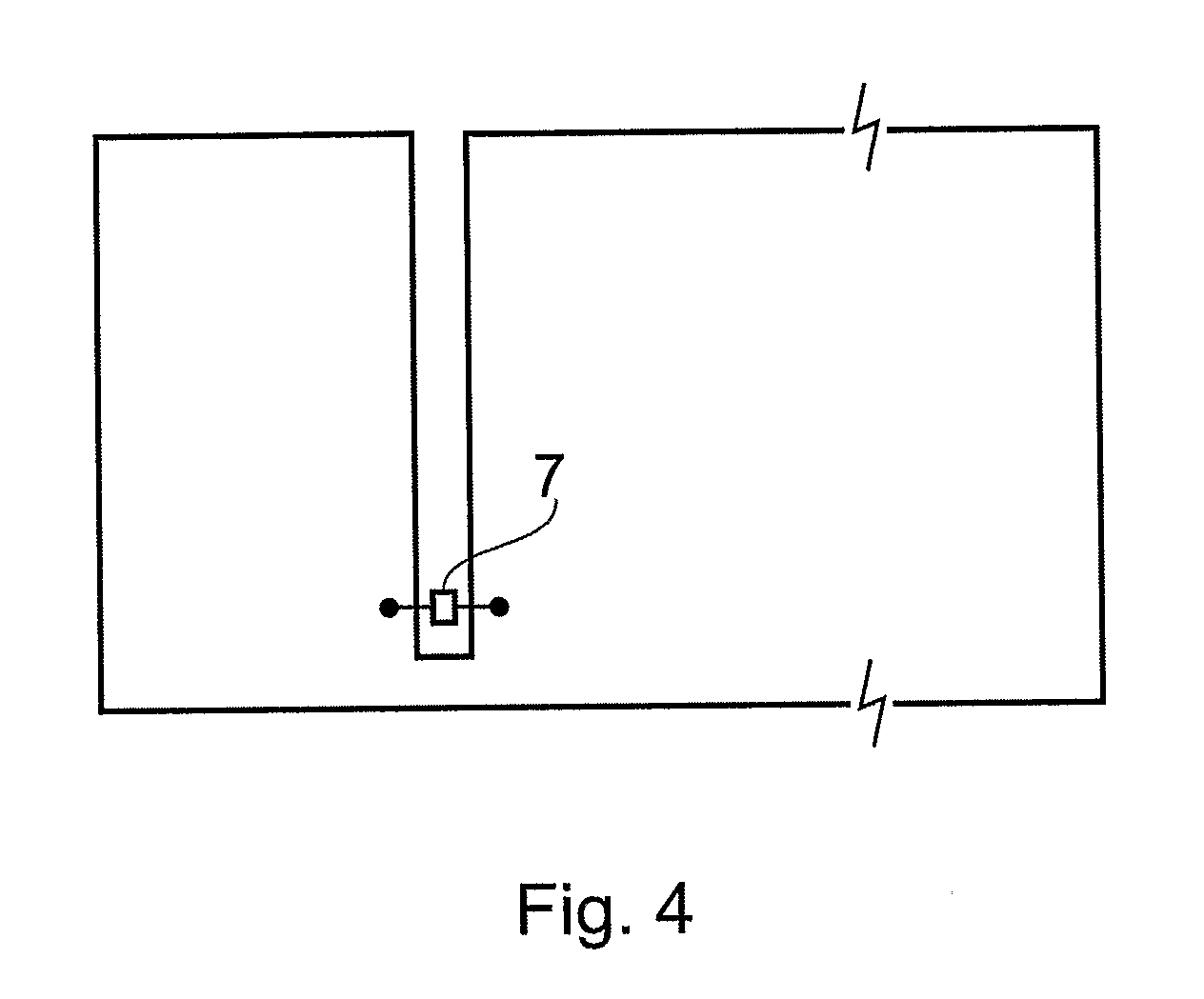
[0017]The Figures schematically illustrate an antenna arrangement 10 comprising: an antenna 2 occupying at least a first plane 6; and a conductive structure 12 that is not electrically connected to the antenna 2 but is parasitically fed by the antenna 2, the conductive structure 12 having a slot 14 and occupying at least a second plane different to but adjacent the first plane.
[0018]In particular, FIGS. 1A and 1B illustrate an apparatus 1 comprising an external conductive housing element 12 that houses an antenna 2. In this example, the housing element 12 forms a conductive structure that almost entirely surrounds a cavity 3 housing the internal antenna 2.
[0019]The conductive housing element 12 comprises a slot 14 that facilitates the transfer of electromagnetic waves between the exterior of the housing 12 and the antenna 2. The slot 14 is defined by the absence of conductive material in the region of the slot 14. The slot 14 may be an open aperture to the interior cavity 3 or it ma...
PUM
 Abstract
Description
Claims
Application Information
 - R&D Engineer
- R&D Manager
- IP Professional
- Industry Leading Data Capabilities
- Powerful AI technology
- Patent DNA Extraction
Browse by: Latest US Patents, China's latest patents, Technical Efficacy Thesaurus, Application Domain, Technology Topic, Popular Technical Reports.
© 2024 PatSnap. All rights reserved.Legal|Privacy policy|Modern Slavery Act Transparency Statement|Sitemap|About US| Contact US: help@patsnap.com