Antenna isolation

a dual-polarized, antenna isolation technology, applied in the structural form of radiating elements, substantially flat resonant elements, resonant antennas, etc., can solve cancel out this specific unwanted signal, and no solution is shown for solving the problem of capacitive coupling related to the feeder itself, etc. problem, to achieve good antenna isolation, small size, and efficient compensation

Active Publication Date: 2009-10-15
INTEL CORP
View PDF13 Cites 20 Cited by
  • Summary
  • Abstract
  • Description
  • Claims
  • Application Information

AI Technical Summary

Benefits of technology

[0015]The present invention aims to provide a dual polarised antenna element, which offers improved antenna isolation for all kinds of essentially capacitive couplings between the feeders. The present invention thus aims to provide compensation for capacitive coupling between the feeders, also including a capacitive coupling occurring via the radiating part, for example a radiating patch, of the antenna element.
[0021]The dual polarised antenna element according to the present invention has the advantage that it can provide good antenna isolation through an efficient compensation for essentially all types of capacitive coupling between the feeders in the antenna element, including capacitive coupling between the feeders and the radiating part of the antenna element. The compensation is achieved by the use of a compensation line, which is small in size, not costly to produce, easy to implement and which efficiently cancels out the capacitive coupling being present by its inductive character.

Problems solved by technology

According to this document, a signal being transmitted from a first antenna element having one polarisation is received by a second antenna element having another polarisation, thereby causing an unwanted signal to be received by the second antenna element.
Prior art solutions like the one described in U.S. Pat. No. 6,509,883, have a disadvantage in that they only compensate for signals having been transmitted from one antenna element and received by another antenna element.
Thus, no solution is shown for solving the problem of capacitive coupling related to the feeders themselves.
The prior art solution will therefore only cancel out this specific unwanted signal.
Also, a capacitive coupling between the feeders may take place at a very unfortunate point, for which a difference in length of an even number of half wavelength results between the paths traveled by the unwanted signal and by the compensation signal in U.S. Pat. No. 6,509,883.
Further, due to the signal path length requirements, the antenna element shown in this document has to have a certain size to achieve efficient cancellation, which is disadvantageous.
Thus, there is a problem in prior art relating to cancellation of different kinds of couplings being present in a dual polarized antenna element.

Method used


Image

  • Antenna isolation
  • Antenna isolation
  • Antenna isolation

Examples


Embodiment Construction

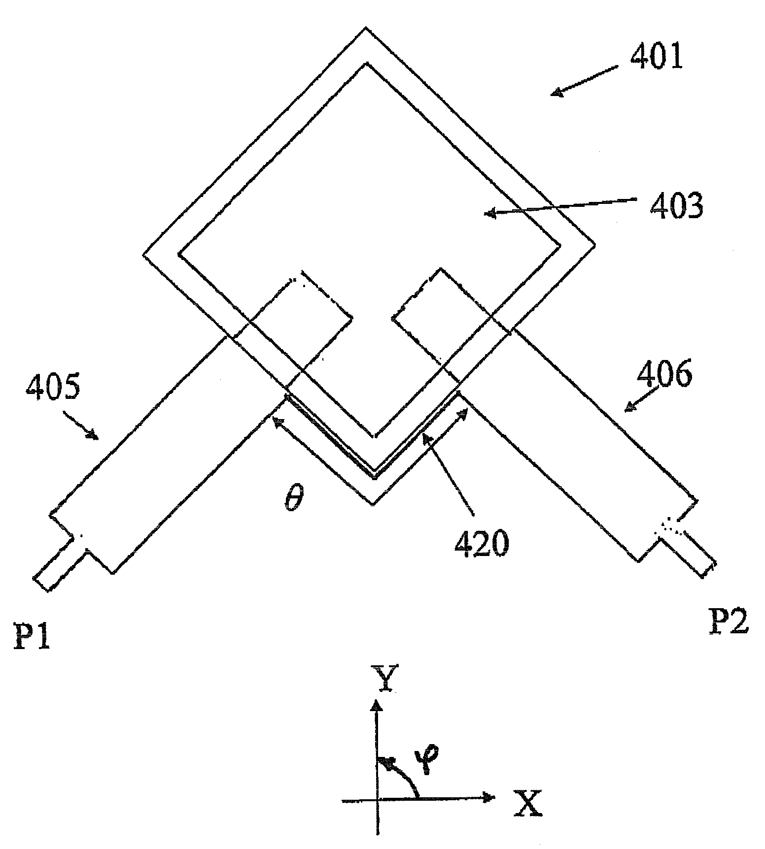
[0034]Dual polarized antenna elements commonly suffer from imbalance due to mutual coupling for various reasons. Even though an antenna element may show a geometrical symmetry to a large extent, including the radiating part and the majority of the feed network, we typically have one or more points of asymmetry causing mutual coupling.

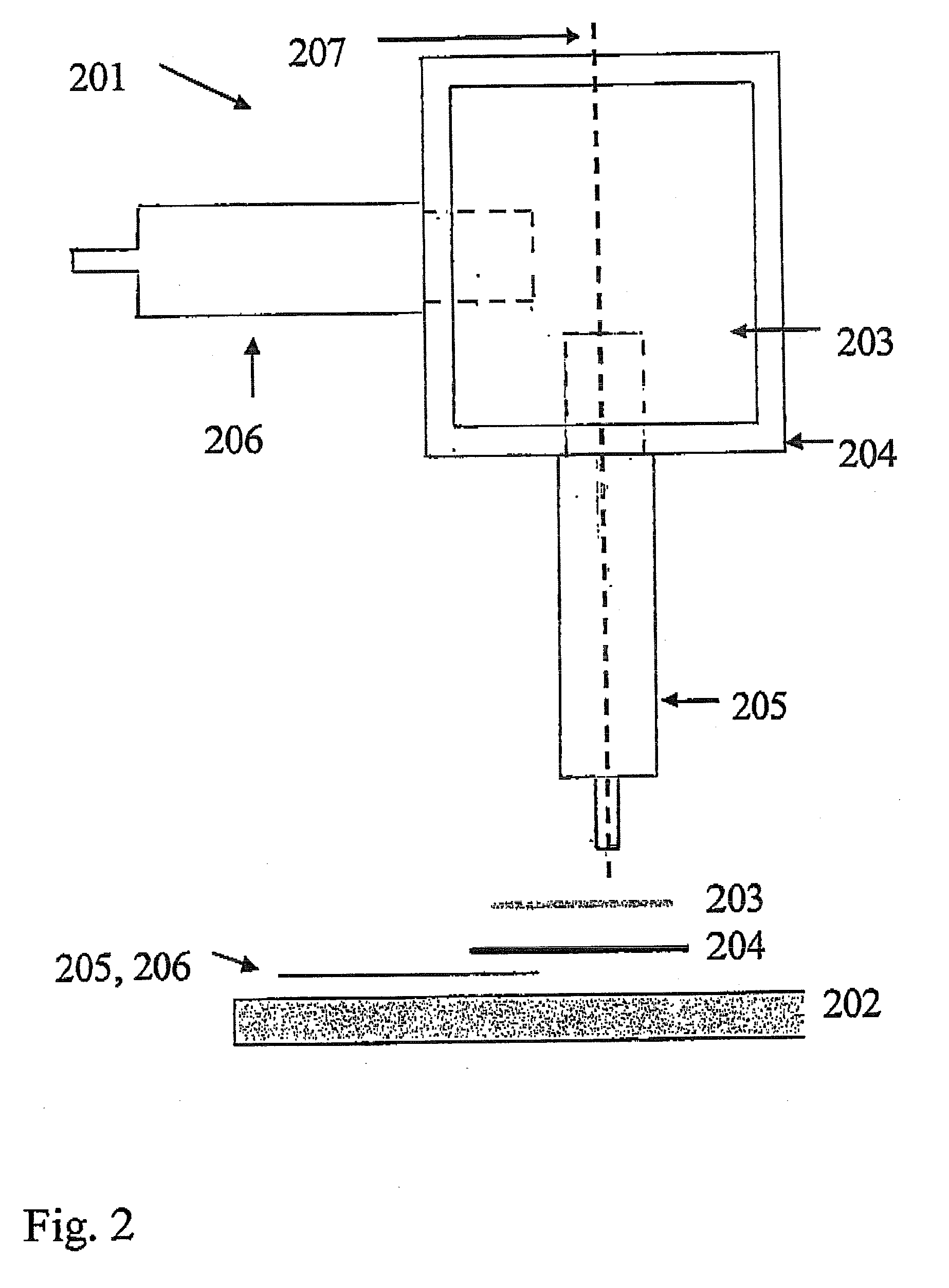
[0035]FIG. 2 shows one example of this for a patch antenna element including a ground plane 202, a top patch 203 and a lower patch 204. Here, an electromagnetically coupled patch element is fed by two orthogonal feeders 205, 206, both with a capacitive coupling to the two stacked patches. The antenna element is here not symmetrical, since the feeder connections are not symmetrical. For example, if we look into the element along for example the feeder 205 at the bottom of the figure, we see that only one side (the left side) of the other sides of each patch is loaded by another feeder 206, while the other sides (for instance the right side) have an open ...


PUM


Abstract

A dual polarized antenna element having improved antenna isolation is disclosed by the present invention. The antenna element includes a first feeder for feeding the antenna element in a first polarization direction, and a second feeder for feeding the antenna element in a second polarization direction. According to the present invention, a compensation line is arranged between the first and the second feeders for compensating for an imbalance caused by an essentially capacitive coupling between the first and second feeders. The compensation line is connected to the first and second feeders in close proximity to a radiating part of said antenna element, and has a short electrical length θ and a high impedance relative to an impedance of the first and second feeders, respectively, thereby giving the compensation line an essentially inductive character.

Description

TECHNICAL FIELD[0001]The present invention relates to a dual polarized antenna element and an antenna array, in which the antenna element includes:[0002]a first feeder for feeding the antenna element in a first polarization direction, and[0003]a second feeder for feeding the antenna element in a second polarization direction.BACKGROUND OF THE INVENTION[0004]Dual polarised or X-polarised antennas are today commonly used in cellular systems for mobile communication. The use of such antennas allows the use of polarisation diversity techniques to combat signal fading in the system. Compared to the use of vertical polarised antennas and space diversity techniques the number of antennas needed is reduced to half, which saves costs and reduces the size and the visual appearance of the antenna installations.[0005]One important performance measure for dual polarised antennas is the isolation between the two antenna ports feeding the two polarisations. Typically, an isolation of more than 30 ...

Claims


Application Information

Patent Timeline
Patent Type & Authority Applications(United States)
IPC IPC(8): H01Q1/50H01Q1/38
CPCH01Q9/045H01Q9/0435
Inventor LINDMARK, BJORN
Owner INTEL CORP
Why Eureka
Try Eureka