Inkjet recording apparatus

a recording apparatus and a technology applied in the field of a recording device, can solve the problems of reducing the ejection performance of the droplet, increasing the pressure loss, and reducing the ejection properties, and achieves the effects of reducing the pressure variation, high pressure adjustment accuracy, and good print quality

Inactive Publication Date: 2010-03-25
FUJIFILM CORP +1
View PDF11 Cites 56 Cited by
  • Summary
  • Abstract
  • Description
  • Claims
  • Application Information

AI Technical Summary

Benefits of technology

[0020]According to this aspect of the invention, it is possible to attenuate pressure variation caused by movement of liquid by means of the flexible films and the gas chambers, and hence this pressure variation is not transmitted to the recording head and therefore good print quality can be ensured. Furthermore, highly accurate pressure adjustment can be achieved.
[0021]According to the present invention, since the filter and/or deaeration apparatus is provided outside the path between the first and second liquid c...

Problems solved by technology

When the ink contains air bubbles, the pressure applied to the ink inside the pressure chamber is absorbed by the air bubbles which have compressive properties, and the ink droplet ejection performance declines.
However, the inkjet recording apparatus described in Japanese Patent Application Publication No. 2007-130907 has problems in that the pressure loss increases as the volume of ink flowing per unit time through the deaeration apparatus becomes greater (in other words, in cases of large flow rate).
Furthermore, since the temperature of the ink is not constant over time, then there is a possibility that the ejection p...

Method used


Image

  • Inkjet recording apparatus
  • Inkjet recording apparatus
  • Inkjet recording apparatus

Examples


first embodiment

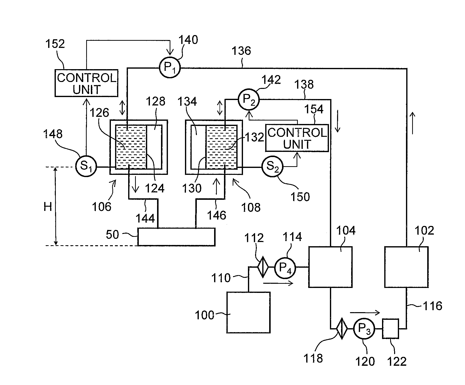
[0082]FIG. 7 is an approximate diagram showing an example of the composition of an ink supply system according to a first embodiment. In FIG. 7, in order to simplify the description, the ink supply system relating to only one color is depicted, but in the case of a plurality of colors, a plurality of similar compositions are provided.

[0083]As illustrated in FIG. 7, the ink supply system relating to the first embodiment principally comprises: a main tank 100, a first buffer tank 102, a second buffer tank 104, a supply sub tank 106 and a recovery sub tank 108.

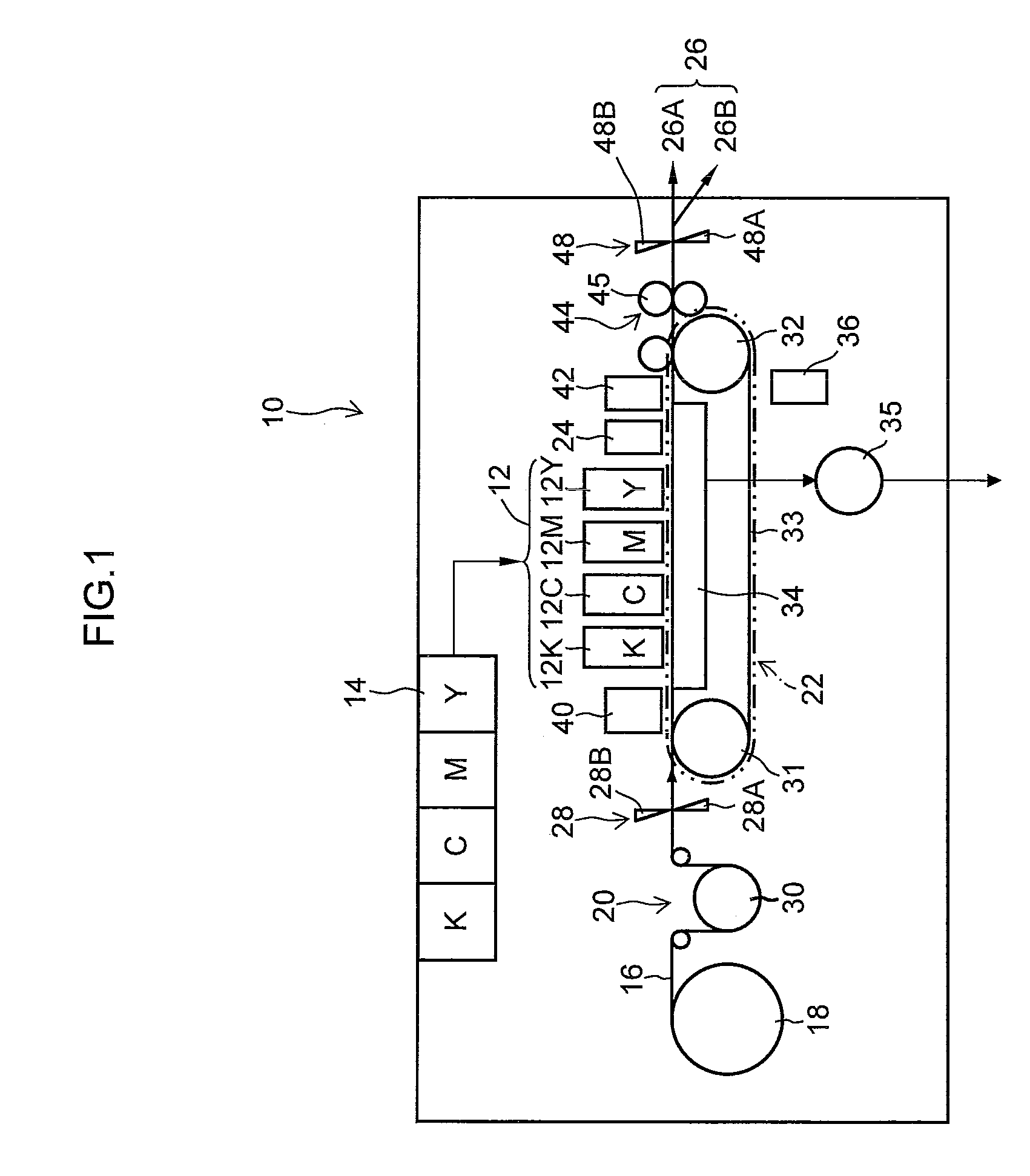
[0084]The main tank 100 is a base tank (ink supply source) which stores ink for supplying to the head 50, and corresponds to the tank which is disposed in the ink storage and loading unit 14 illustrated in FIG. 1. The main tank 100 is connected to a second buffer tank 104 via the flow channel 110. The main tank 100 may be connected to the first buffer tank 102 instead of the second buffer tank 104. A filter 112 and a main pump 11...

second embodiment

[0107]Next, a second embodiment of the present invention will be described. Below, portions which are common with the first embodiment are not explained further, and the following description centers on the characteristic features of the present embodiment.

[0108]FIG. 8 is an approximate diagram illustrating an example of the composition of an ink supply system according to a second embodiment. In FIG. 8, parts which are common with FIG. 7 are labeled with the same reference numerals.

[0109]As illustrated in FIG. 8, the ink supply system relating to the second embodiment principally comprises: a main tank 100, a buffer tank 200, a supply sub tank 106 and a recovery sub tank 108. In other words, whereas, in the first embodiment, two buffer tanks are provided, the second embodiment differs from this in that one buffer tank is provided.

[0110]The main tank 100 and the buffer tank 200 are connected via the flow channel 110. A filter 112 and a main pump 114 are provided in the flow channel ...


PUM


Abstract

An inkjet recording apparatus includes: a recording head including an introduction section, a discharge section and nozzles; a first liquid chamber connected to the introduction section; a second liquid chamber connected to the discharge section; a first buffer tank which is connected to the first liquid chamber and an interior of which is open to air; a second buffer tank which is connected to the second liquid chamber and an interior of which is open to air; and a pressure control device which sets target pressures of the first liquid chamber and the second liquid chamber in such a manner that a prescribed back pressure is applied to the liquid inside the nozzles of the recording head while a prescribed pressure differential is provided between the first liquid chamber and the second liquid chamber, and controls driving of the first pump and the second pump in accordance with determination results of the pressure determination device in such a manner that the internal pressures of the first liquid chamber and the second liquid chamber remain constant at the target pressures, wherein the first buffer tank and the second buffer tank are connected via a flow channel, and at least one of a filter and a deaeration device is provided in the flow channel.

Description

BACKGROUND OF THE INVENTION[0001]1. Field of the Invention[0002]The present invention relates to an inkjet recording apparatus, and more particularly, to ink supply technology which enables highly accurate control of back pressure even in the case of ink of high viscosity and large flow volume.[0003]2. Description of the Related Art[0004]Conventionally, an inkjet recording apparatus is known which comprises an inkjet type of recording head having a plurality of nozzles and which records a desired image on a recording medium by ejecting ink droplets respectively from the nozzles in accordance with input image data. The ink ejection method may be a piezoelectric method in which ink droplets are ejected from nozzles by utilizing the displacement of piezoelectric elements to pressurize the ink inside pressure chambers, or a thermal method in which ink droplets are ejected from nozzles due to the pressure created by the growth of gas bubbles which are generated inside pressure chambers b...

Claims


Application Information

Patent Timeline
IPC IPC(8): B41J2/175
CPCB41J2/17556B41J2/17509
Inventor SHIBATA, HIROSHIKATADA, MASAHITOMURAKAMI, ATSUSHIKATADA, YUKO
Owner FUJIFILM CORP
Why Eureka
Try Eureka