Stereoscopic image capturing apparatus and stereoscopic image capturing system

a technology of stereoscopic image and capturing system, which is applied in the field of stereoscopic image capturing apparatus and stereoscopic image capturing system, can solve the problems of inability to generate multi-parallax images with high picture quality, individual differences in installation precision of respective systems, and the degradation of picture quality, so as to achieve the effect of reducing data quantity and high picture quality

Inactive Publication Date: 2010-03-25
KK TOSHIBA
View PDF8 Cites 148 Cited by
  • Summary
  • Abstract
  • Description
  • Claims
  • Application Information

AI Technical Summary

Benefits of technology

[0010]The present invention has been made in view of these circumstances, and an object thereof is to provide a stereoscopic image capturing apparatus and a stereoscopic...

Problems solved by technology

If a large number of cameras are used, then the picture quality is degraded by individual differences and installation precisions of respective cameras.
In the movable cameras, dispersion among systems which drive the movable cameras poses a problem.
In this stereoscopic image capturing apparatus, problems such as location deviations or individual differences of camera are not posed, because multi-parallax information is capture by one image sensor.
In the method (JP-A 10-224820), however, there is a feature to...

Method used


Image

  • Stereoscopic image capturing apparatus and stereoscopic image capturing system
  • Stereoscopic image capturing apparatus and stereoscopic image capturing system
  • Stereoscopic image capturing apparatus and stereoscopic image capturing system

Examples


first embodiment

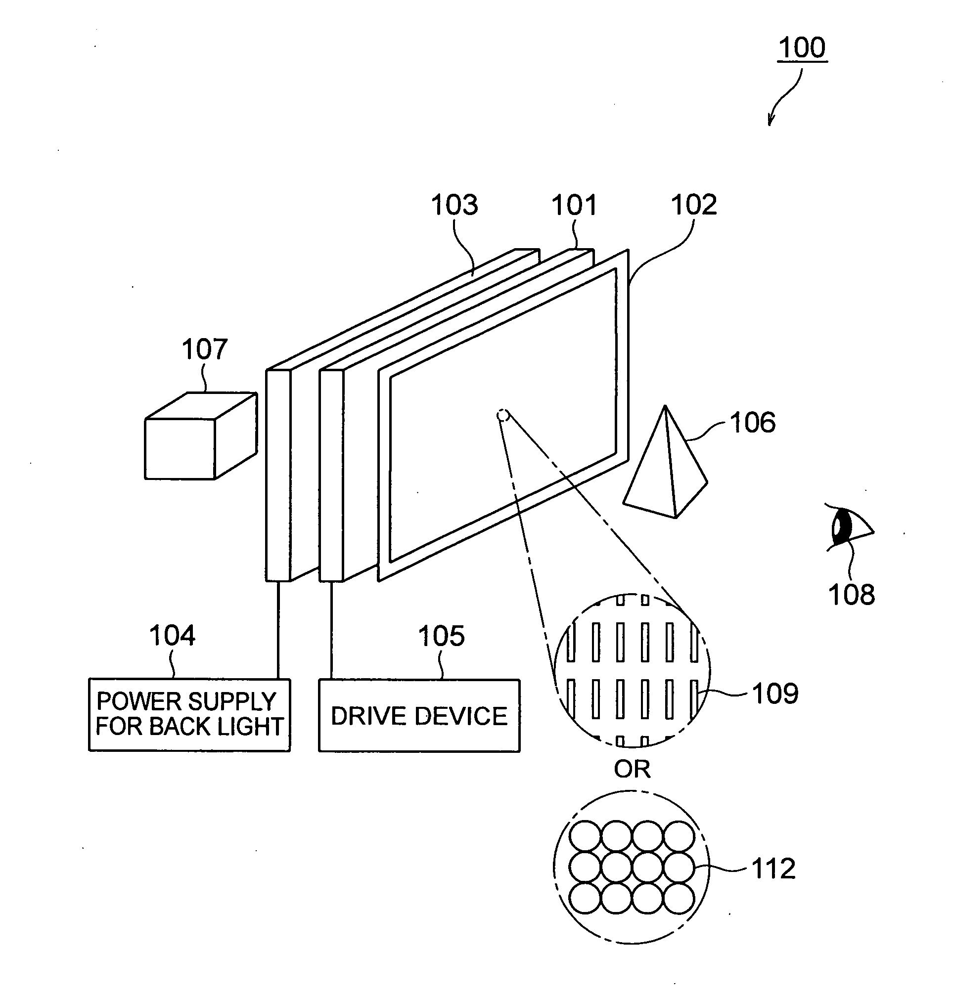
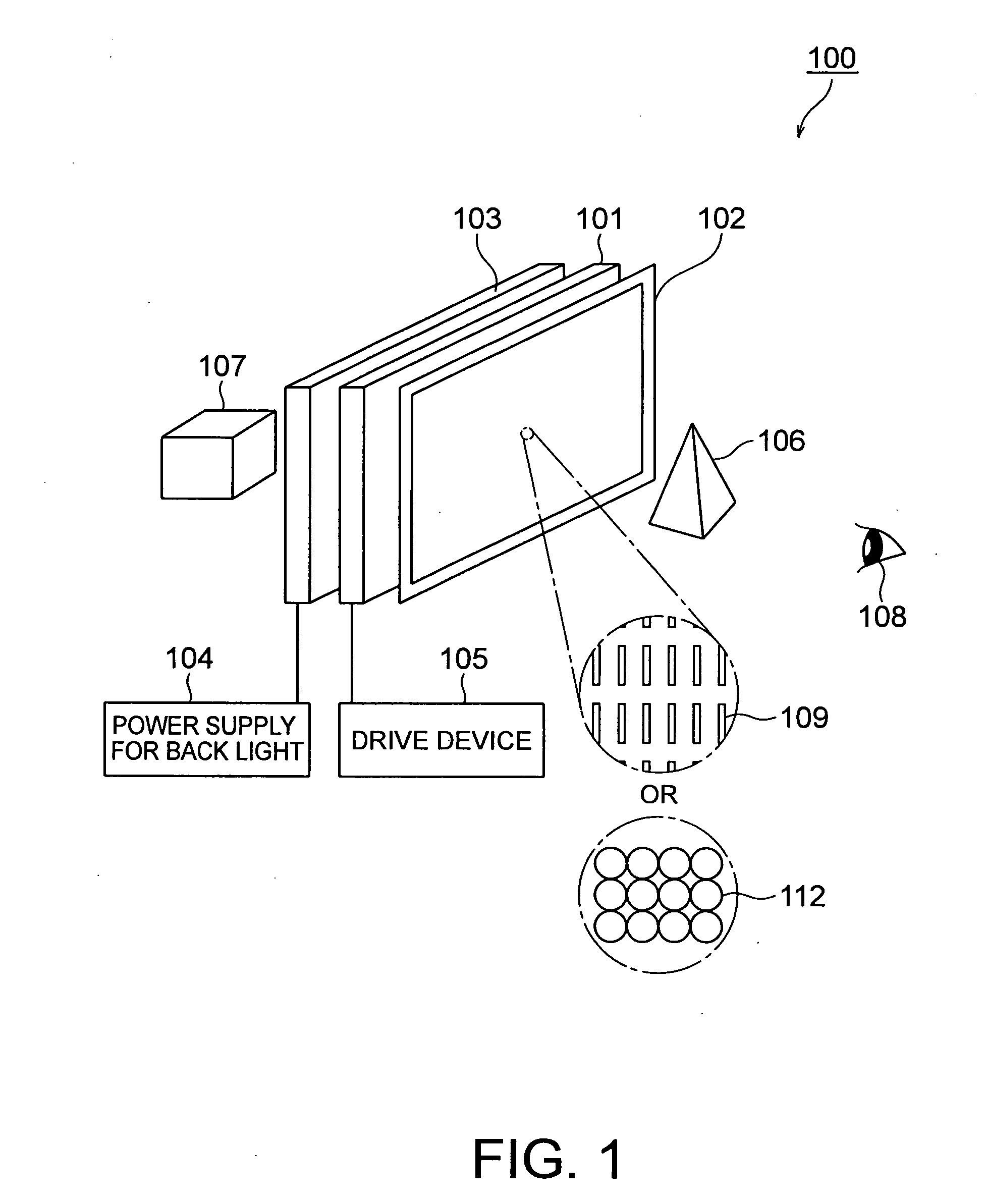
[0057]A stereoscopic image capturing apparatus according to a first embodiment of the present invention is shown in FIG. 1. FIG. 5 is a plan view of the stereoscopic image capturing apparatus according to the present embodiment. The stereoscopic image capturing apparatus according to the present embodiment includes a lens array camera 10 and a camera 20. These cameras 10 and 20 are arranged so as to line up in the horizontal direction when viewed from an object 200 and so as to be common in an imaging area. The lens array camera 10 includes an image sensor 12 having photoelectric conversion elements, such as CCDs or CMOSs, (hereafter referred to as capturing pixels or simply pixels as well) capable of capturing a two-dimensional image arranged in a matrix form, a lens array 14 provided in the front of the image sensor 12, and an optical system including an image formation lens 16 to focus light rays from an object to be captured on an image sensor 12 thorough the lens array 14. The ...

second embodiment

[0069]A stereoscopic image capturing apparatus according to a second embodiment of the present invention will now be described with reference to FIGS. 9 and 10. FIG. 9 is a plan view of the stereoscopic image capturing apparatus according to the present embodiment. FIG. 10 is a front view of the stereoscopic image capturing apparatus obtained when viewed from a direction of an arrow z (direction of the object) shown in FIG. 9. The stereoscopic image capturing apparatus according to the present embodiment includes two lens array cameras 101 and 102 and a camera 20. In other words, the present embodiment has a configuration obtained by providing one additional lens array camera in the first embodiment. The lens array cameras 101 and 102 are disposed on the left and right sides of the camera 20 in the horizontal direction when viewed from the object. In other words, a base line 301 between the lens array camera 101 and the camera 20 and a base line 302 between the lens array camera 102...

third embodiment

[0071]A stereoscopic image capturing apparatus according to a third embodiment of the present invention will now be described with reference to FIG. 11. FIG. 11 is a front view of the stereoscopic image capturing apparatus according to the present embodiment obtained when viewed from the object. The stereoscopic image capturing apparatus according to this embodiment has a configuration obtained from that of the stereoscopic image capturing apparatus according to the second embodiment by arranging the lens array cameras 101 and 102 and the camera 20 so as to cause a base line 30, between the lens array camera 101 and the camera 20 to be nearly perpendicular to a base line 302 between the lens array camera 102 and the camera 20. In other words, when viewed from the object, the lens array camera 101 is disposed in the horizontal direction of the camera 20 and the lens array camera 102 is disposed in the vertical direction of the camera 20. Ridgelines of cylindrical lenses in the lens a...


PUM


Abstract

A stereoscopic image capturing apparatus includes a first image acquisition unit including a first image formation lens unit forming an image of an object, and a first image sensor having a plurality of capturing pixels to receive the image formed by the first formation lens unit, and a second image acquisition unit including a second image formation lens unit forming a image of the object, a first lens array unit having a plurality of lenses to receive the image formed by the second image formation lens, and a second image sensor having a plurality of capturing pixels to receive the formed image through the first lens array unit. The second image acquisition unit is disposed at a distance in a horizontal direction from the first image acquisition unit when viewed from the object.

Description

CROSS-REFERENCE TO RELATED APPLICATION[0001]This application is based upon and claims the benefit of priority from prior Japanese Patent Application No. 2008-245502 filed on Sep. 25, 2008 in Japan, the entire contents of which are incorporated herein by reference.BACKGROUND OF THE INVENTION[0002]1. Field of the Invention[0003]The present invention relates to a stereoscopic image capturing apparatus and system for obtaining stereoscopic image information to be displayed on a display.[0004]2. Related Art[0005]A large number of cameras, movable cameras, or laser scans are used to acquire stereoscopic image information of an object having a depth. If a large number of cameras are used, then the picture quality is degraded by individual differences and installation precisions of respective cameras. In the movable cameras, dispersion among systems which drive the movable cameras poses a problem.[0006]Therefore, a stereoscopic image capturing apparatus using stereo cameras is proposed (JP-...

Claims


Application Information

Patent Timeline
IPC IPC(8): H04N13/02H04N13/239
CPCG02B27/2214G06T7/0022H04N13/0409H04N13/0239H04N13/0029H04N13/31H04N13/239H04N13/139G02B30/27
Inventor MOMONOI, YOSHIHARUIWANAKA, YUKI
Owner KK TOSHIBA
Why Eureka
Try Eureka