Beam irradiation apparatus

a beam irradiation and beam technology, applied in the direction of navigation instruments, instruments for comonautical navigation, instruments, etc., can solve the problems of distortion in the intensity distribution of laser beams, lens actuators susceptible to vibration from the outside, and the beam swing angle is not increased too large, so as to reduce weight and enhance the response characteristic of the mirror

Inactive Publication Date: 2010-03-25
SANYO ELECTRIC CO LTD +1
View PDF1 Cites 18 Cited by
  • Summary
  • Abstract
  • Description
  • Claims
  • Application Information

AI Technical Summary

Benefits of technology

[0017]In the beam irradiation apparatus according to the aspect of the present invention, preferably the electromagnetic driving unit includes first and second coils which are provided in the mirror holder and the first retaining member respectively; and first and second magnets which are disposed in the

Problems solved by technology

Additionally, because the mirror surface has a small angle change with respect to a laser beam axis, unfortunately a swing angle of the laser beam is not increased too large.
However, because the lens is supported by a plate spring or a wire, unfortunately the lens a

Method used


Image

  • Beam irradiation apparatus
  • Beam irradiation apparatus
  • Beam irradiation apparatus

Examples


Embodiment Construction

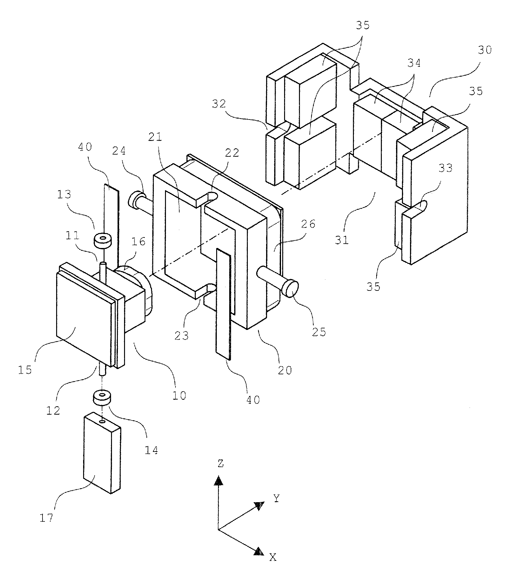
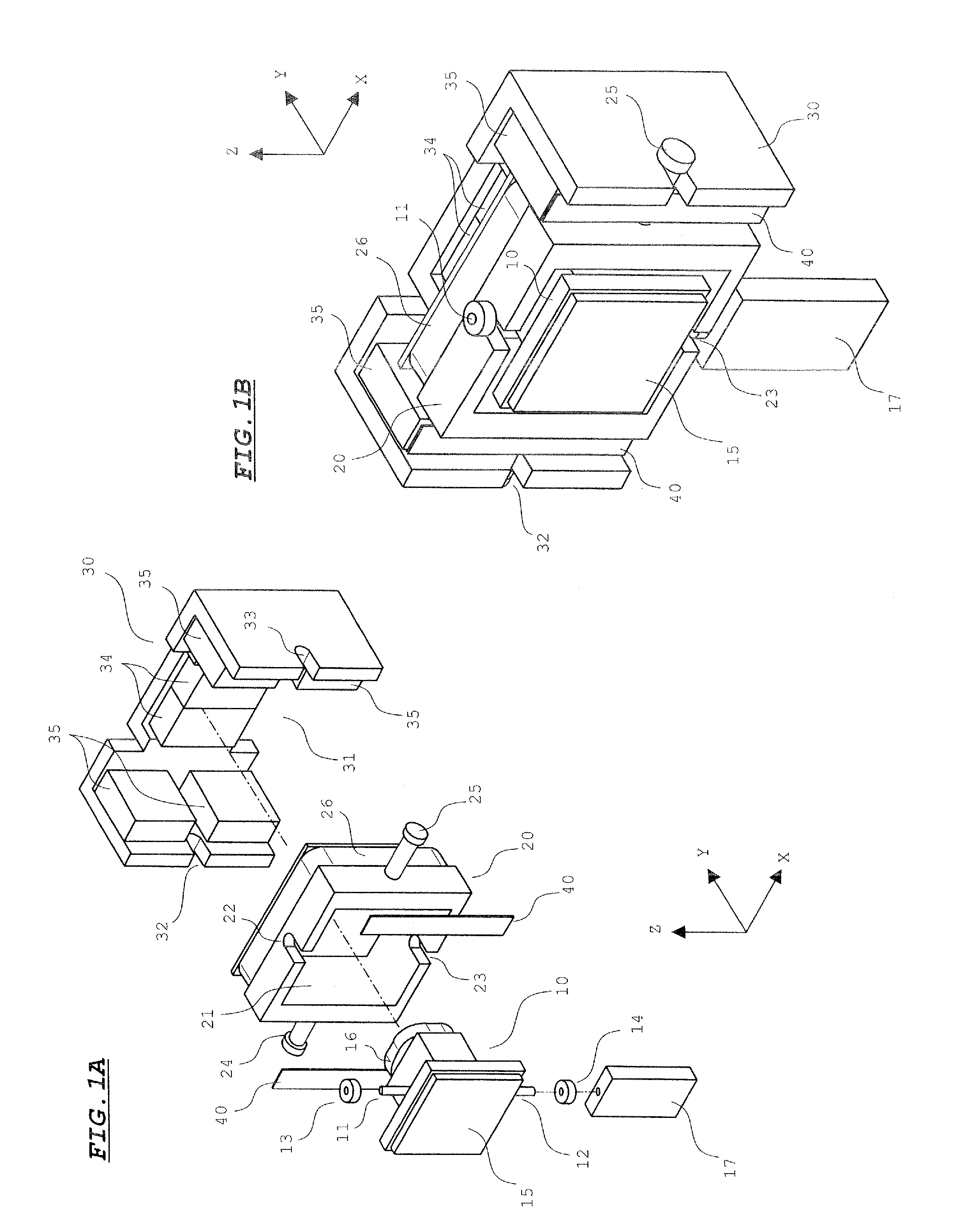
[0027]FIG. 1 shows a configuration of a beam irradiating actuator according to an embodiment of the present invention. FIG. 1A is an exploded perspective view of the actuator and FIG. 1B is a perspective view showing the actuator in an assembled state.

[0028]Referring to FIG. 1A, support shafts 11 and 12 are formed in a mirror holder 10, and bearings 13 and 14 are attached in end portions of the support shafts 11 and 12. The support shaft 12 is inserted and attached in the bearing 14 while the end portion of the bearing 14 is projected. A mirror 15 is attached to a front surface of the mirror holder 10, and a coil 16 is attached to the backside of the mirror holder 10. The coil 16 is wounded in a rectangular shape. A parallel plate light refracting element 17 is attached to the end portion of the support shaft 12 of the mirror holder 10. The light refracting element 17 is made of a translucent material.

[0029]The mirror holder 10 is journaled in a movable frame (first retaining member...


PUM


Abstract

A light refracting element formed in parallel plate shape is attached to a support shaft of a mirror holder, a semiconductor laser and a PSD are disposed at positions between which the light refracting element is sandwiched. The light refracting element is rotated by rotation of the mirror holder, and whereby a laser beam irradiation position is changed on a light acceptance surface of PSD. The laser beam irradiation position on a light acceptance surface corresponds to the mirror rotation position, so that the mirror rotation position and a laser beam scanning position in a target area can be detected based on an output from the PSD.

Description

[0001]This application claims priority under 35 U.S.C. Section 119 of Japanese Patent Application No. 2007-062924 filed Mar. 13, 2007, entitled “BEAM IRRADIATION APPARATUS”.BACKGROUND OF THE INVENTION[0002]1. Field of the Invention[0003]The present invention relates to a beam irradiation apparatus which irradiates a target area with a laser beam, particularly to a beam irradiation apparatus mounted on so-called laser radar which detects existence of an obstacle within the target area and a distance to the obstacle based on reflected light in irradiating the target area with the laser beam.[0004]2. Description of the Related Art[0005]Recently, a laser radar is mounted on an automobile for family use or the like in order to enhance safety during running. In the laser radar, the front in the running direction is irradiated with a laser beam, and existence of an obstacle in a target area and a distance to the obstacle is detected based on the state of the reflected light. Usually, in th...

Claims


Application Information

Patent Timeline
IPC IPC(8): G02B26/10
CPCG01S7/4811G01S7/4816G01S7/4817G02B26/101G01S17/48G01S17/936G02B26/0875G01S7/491G01S17/931
Inventor YAMAGUCHI, ATSUSHIYAMADA, MASATOMAENO, YOSHIAKI
Owner SANYO ELECTRIC CO LTD
Why Eureka
Try Eureka