
Light emitting diode bulb

a technology of light-emitting diodes and led light-emitting bulbs, which is applied in the direction of transportation and packaging, semiconductor devices of light sources, lighting and heating apparatus, etc., can solve the problems of insufficient heat dissipation efficiency achieve effective heat dissipation efficiency, improve the working efficiency and reliability of led light-emitting bulbs

Inactive Publication Date: 2010-03-25
EDISON-OPTO
View PDF6 Cites 98 Cited by
  • Summary
  • Abstract
  • Description
  • Claims
  • Application Information

AI Technical Summary

Benefits of technology

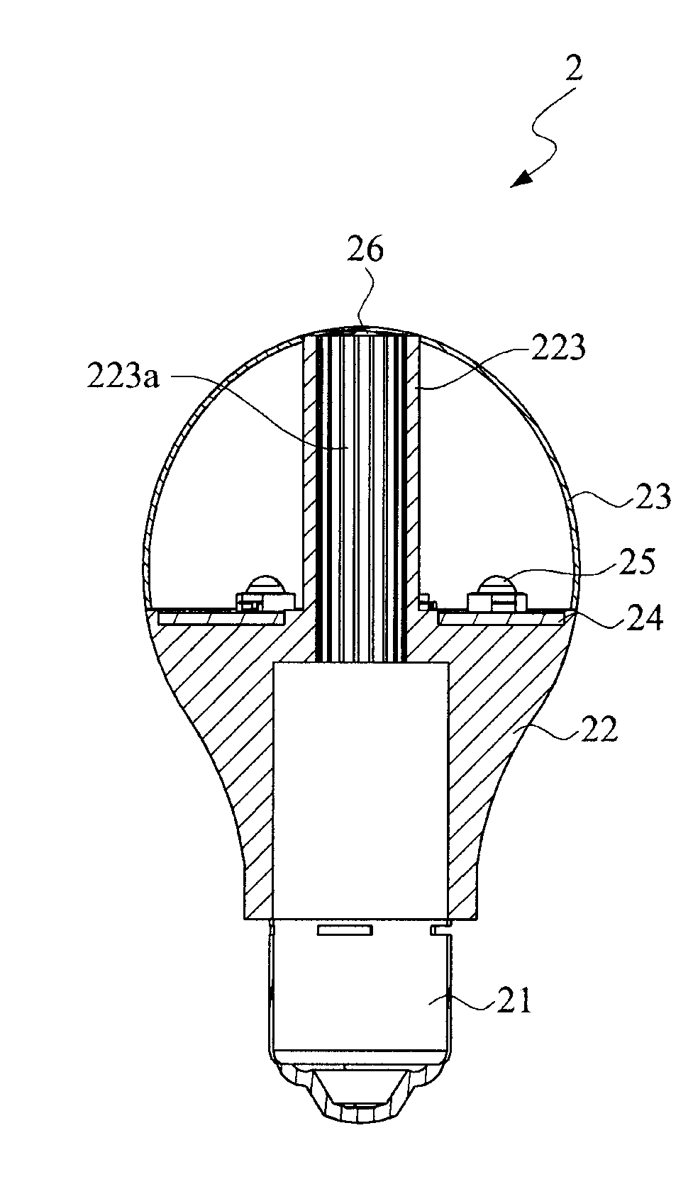
[0010]Means of the present invention for solving the problems as mentioned above provides a light emitting diode (LED) light bulb. The LED light bulb comprises a heat dissipation module, a circuit board, at least one LED light source and a light-transmissible packaging shell. The heat dissipation module comprises a heat dissipation base and a heat convection tube extended from the heat dissipation base. The circuit board is assembled to the heat dissipation module. The LED light source is arranged on the circuit board, and releases heat energy when projecting at least one illumination light beam. The light-transmissible packaging shell is assembled to the heat dissipation module to package the LED light source, and formed with a heat dissipation opening. The heat convection tube is extended to the heat dissipation opening to communicate with external environment, so that a heat convection action is progressed between the heat convection tube and external environment to dissipate heat energy. Comparing with the conventional LED light bulb as disclosed in prior arts, in the present invention, the heat dissipation module comprises a heat convection tube communicating with external environment, so that a heat convection action can be progressed to provide another heat dissipation path to effectively raise the heat efficiency of heat dissipation, and to further improve the working efficiency and reliability of the LED light bulb.

Problems solved by technology

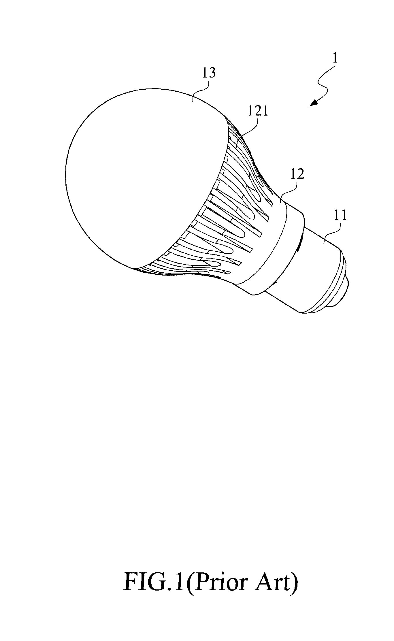
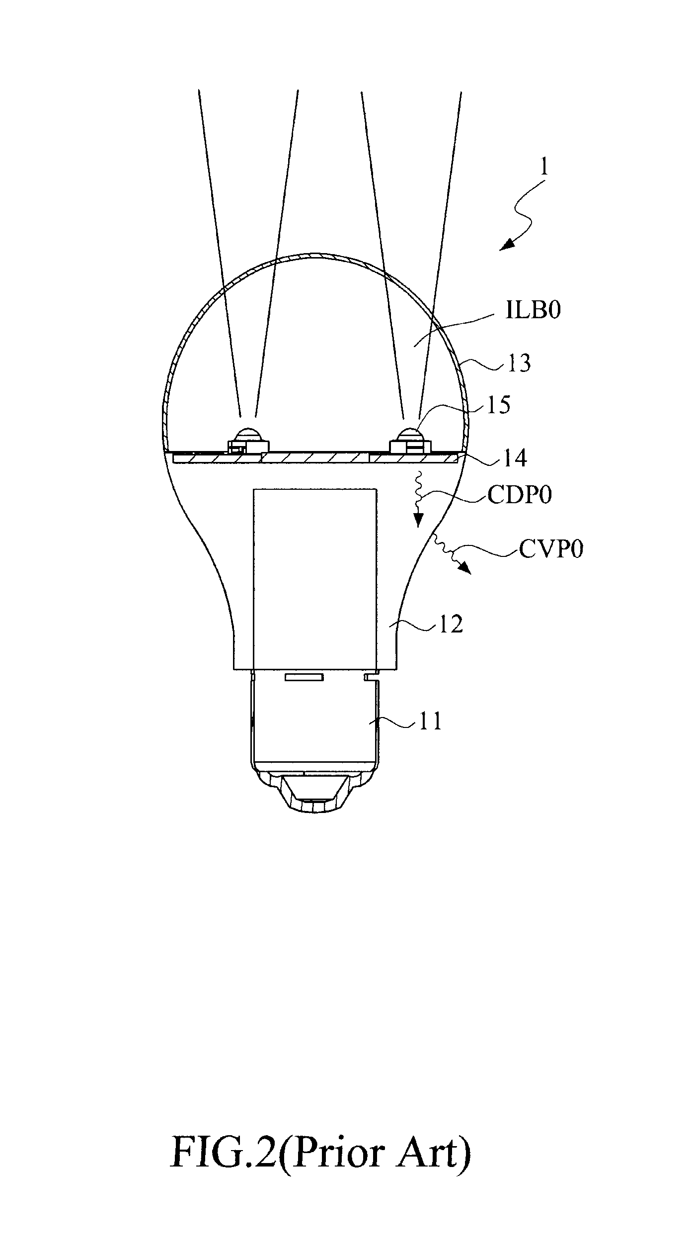
In prior arts, the efficiency of heat dissipation of the LED light bulb is insufficient.

Method used


Image

  • Light emitting diode bulb
  • Light emitting diode bulb
  • Light emitting diode bulb

Examples


Embodiment Construction

[0019]The LED light bulb as disclosed in the present invention can be widely used to replace the conventional incandescent light bulbs, compact fluorescent lamp and the existed LED light bulbs, and the combined applications of the present invention are too numerous to be enumerated and described. Therefore, only a preferred embodiment is disclosed as follows for representation.

[0020]Please refer to FIG. 3 to FIG. 5, wherein FIG. 3 is a partially exploded view of an LED light bulb in accordance with a preferred embodiment of the present invention; FIG. 4 is a perspective view of the LED light bulb in accordance with the preferred embodiment of the present invention; and FIG. 5 illustrates the inner structure of the LED light bulb in accordance with the preferred embodiment of the present invention. As shown in the figures, an LED light bulb 2 comprises a bottom base 21, a heat dissipation module 22, a light-transmissible packaging shell 23, a circuit board 24, a plurality of LED ligh...


PUM


Abstract

A light emitting diode (LED) light bulb comprising a heat dissipation module, a circuit board, at least one LED light source and a light-transmissible packaging shell is disclosed in the present invention. The heat dissipation module comprises a heat dissipation base and a heat convection tube extended from the heat dissipation base. The circuit board is assembled to the heat dissipation module. The LED light source is arranged on the circuit board, and releases heat energy when projecting at least one illumination light beam. The light-transmissible packaging shell is assembled to the heat dissipation module to package the LED light source, and formed with a heat dissipation opening. The heat convection tube is extended to the heat dissipation opening to communicate with external environment, so that a heat convection action is progressed between the heat convection tube and external environment to dissipate heat energy.

Description

FIELD OF THE INVENTION[0001]The present invention relates to a light emitting diode light bulb, and more particularly to a light emitting diode light bulb comprising a heat convection tube for dissipating heat energy.BACKGROUND OF THE INVENTION[0002]Light Emitting Diode (LED) is an electronic element, which can radiate light when applying electric power. The lighting principle of LED is translating electric power to light energy, that is, doping a minute amount of carriers into a conjunction of P-type side and N-type side and continuously combining the minute amount of carriers with a major amount of carriers to form a LED. In order to achieve a higher performance of the LED, the process may need a large amount of pairs of electrons and holes. The space charge layers become narrower when applying a forward biased voltage, and then a major amount of carriers are doped into the P-type side and the N-type side according to Fermi characteristic energy level deviation. Due to that the mi...

Claims


Application Information

Patent Timeline
IPC IPC(8): F21V29/00
CPCF21Y2101/02F21V3/02F21V29/773F21K9/135F21V29/506F21Y2103/022F21K9/232F21Y2103/33F21Y2115/10
Inventor CHEN, PIN-CHUN
Owner EDISON-OPTO
Learn More