Base station device and radio communication device

a radio communication device and base station technology, applied in the field of base station devices and radio communication devices, to achieve the effect of high frequency utilization efficiency communication

Inactive Publication Date: 2010-03-25
PANASONIC INTELLECTUAL PROPERTY CORP OF AMERICA
View PDF10 Cites 44 Cited by
  • Summary
  • Abstract
  • Description
  • Claims
  • Application Information

AI Technical Summary

Benefits of technology

[0028]The present invention makes possible frequency scheduling by means of a high-channel-quality frequency for

Problems solved by technology

However, in the case of a cellular system, adaptive modulation and frequency scheduling are necessary

Method used


Image

  • Base station device and radio communication device
  • Base station device and radio communication device
  • Base station device and radio communication device

Examples


embodiment 3

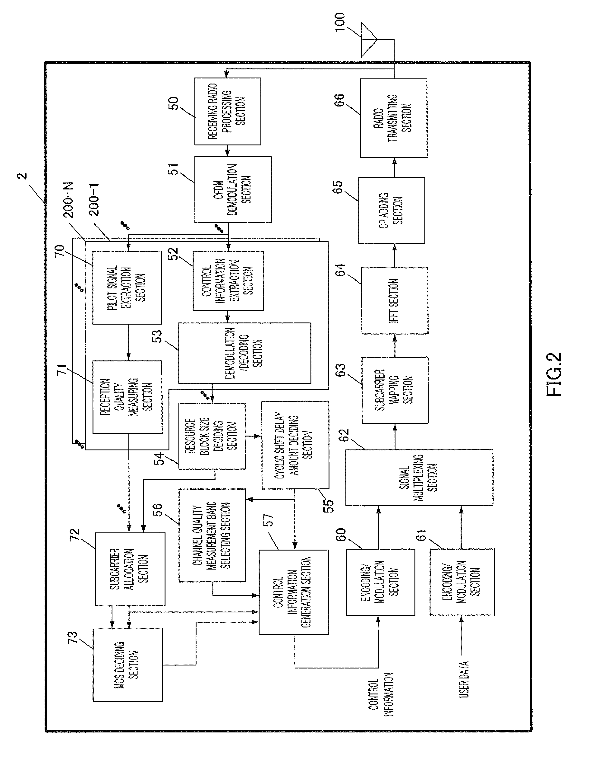
[0255]FIG. 6 is a block diagram showing the configuration of radio communication apparatus 1b according to Embodiment 3, and FIG. 7 is a block diagram showing the configuration of base station apparatus 2b configuring a radio communication system together with radio communication apparatus 1b in FIG. 6.

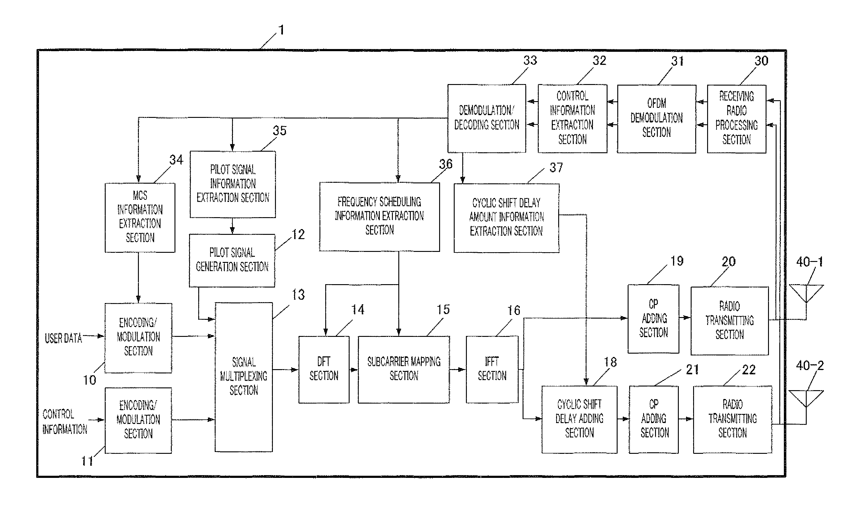
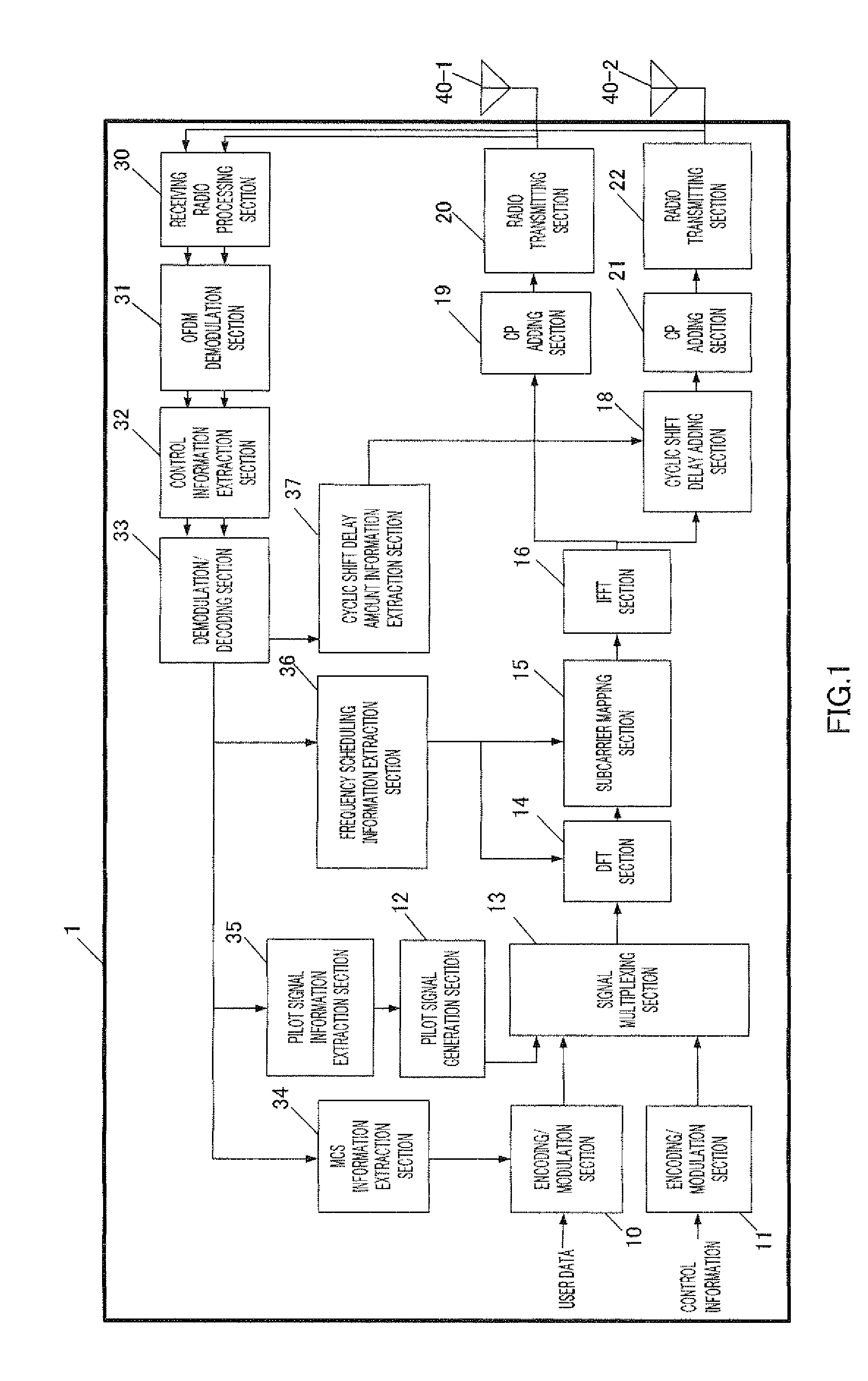
[0256]This radio communication apparatus 1b has a similar basic configuration to that of radio communication apparatus 1 according to Embodiment 1 shown in FIG. 1, and therefore identical configuration elements are assigned the same reference codes, descriptions thereof are omitted here, and only points of difference are described.

[0257]Radio communication apparatus 1b differs from radio communication apparatus 1 according to Embodiment 1 shown in FIG. 1 in additionally including subcarrier phase rotation amount information extraction section 41 and subcarrier phase rotation section 42.

[0258]In radio communication apparatus 1b shown in FIG. 6, subcarrier phase rotation amount informat...

embodiment 4

[0334]FIG. 10 is a block diagram showing the configuration of radio communication apparatus 1c according to Embodiment 4 of the present invention.

[0335]The configuration of radio communication apparatus 1c shown in FIG. 10 differs from that of radio communication apparatus 1 according to Embodiment 1 shown in FIG. 1 in being additionally equipped with delay extent detection section 46 and CSD transmission control section 47, and controlling a shift delay amount of cyclic shift delay adding section 18. Below, identical configuration elements are assigned the same reference codes and descriptions thereof are omitted, and only points of difference in operation are described.

[0336]Delay extent detection section 46 detects a delay extent by calculating a delay extent by detecting a delay profile by means of a method based on autocorrelation using a CP, or cross-correlation using a known signal pattern, using a baseband signal output from receiving radio processing section 30, and outputs...

embodiment 1

Sample Variant of Embodiment 1

[0355]In Embodiment 1, the description given assumes that CSD transmission is performed by radio communication apparatus 1. That is to say, a radio communication apparatus capable of signal transmission from a plurality of antennas is assumed, but for a radio communication apparatus for which signal transmission from a plurality of antennas is difficult, CSD transmission would not be used and signal transmission would be performed from one antenna. In this case, the effect of this embodiment is not obtained by a radio communication apparatus for which CSD transmission is difficult, but there is no particular adverse effect on another radio communication apparatus capable of CSD transmission. Alternatively, another method is to perform transmission that provides a cyclical frequency response to a transmitted signal using the configuration shown in FIG. 13.

[0356]A description is given below of operations in FIG. 13 different from operations based on above...


PUM


Abstract

Provided is a base station device capable of suppressing power consumption of a radio communication device and transmitting a pilot signal for measuring an uplink channel quality in a high frequency use efficiency. The base station device (2) includes: a resource block size decision unit (54) which decides the number of subcarriers to be allocated for the radio communication device (1); and a cyclic shift delay amount decision unit (55) which sets a cyclic shift delay amount used when performing cyclic shift delay diversity transmission according to the number of subcarriers decided by the resource block size decision unit (54). By using the cyclic shift delay amount set by the cyclic shift delay amount decision unit (55), the radio communication device (1) cyclic shift delay diversity transmission of the channel quality measuring signal.

Description

TECHNICAL FIELD[0001]The present invention relates to a base station apparatus and radio communication apparatus that perform high-speed packet communication using frequency resource scheduling and adaptive modulation in a communication system that uses a multiple access method.BACKGROUND ART[0002]In a conventional radio communication system performing high-speed packet transmission, a downlink that transmits a signal from a base station to a radio communication apparatus, and an uplink that transmits a signal from a radio communication apparatus to a base station, are divided, and are estimated by measuring the quality of the respective transmission paths (hereinafter referred to as “channel quality”). Based on this estimated channel quality, the base station performs scheduling that allocates frequency and time resources to an accessed radio communication apparatus, and also sets transmission power and transmission speed (an M-ary value and a coding rate) and transmits data.[0003]...

Claims


Application Information

Patent Timeline
IPC IPC(8): H04W72/08H04W64/00H04W72/04H04W88/08
CPCH04B7/0671H04L5/0007H04W72/085H04L5/006H04L27/2607H04L5/0044H04W72/542
Inventor KISHIGAMI, TAKAAKIOKAMURA, SHUTAI
Owner PANASONIC INTELLECTUAL PROPERTY CORP OF AMERICA
Why Eureka
Try Eureka