Pivot arm tensioner with sliding ratchet mechanism

a ratcheting mechanism and pivoting arm technology, applied in the field of ratcheting tensioner systems, can solve the problems of reducing the service life of the engine, affecting the operation of the mechanical apparatus, and affecting the operation of the engine,

Inactive Publication Date: 2010-03-25
BORGWARNER INC
View PDF15 Cites 4 Cited by
  • Summary
  • Abstract
  • Description
  • Claims
  • Application Information

AI Technical Summary

Problems solved by technology

Prevention of such slippage is particularly important in the case of a chain-driven camshaft in an internal combustion engine because jumping of teeth will throw off the camshaft timing, possibly causing damage or rendering the engine inoperative.
However, in the harsh environment of an internal combustion engine, various factors can cause fluctuations in the chain tension.
For instance, wide variations in temperature and thermal expansion coefficients among the various parts of the engine can cause the chain tensi

Method used


Image

  • Pivot arm tensioner with sliding ratchet mechanism
  • Pivot arm tensioner with sliding ratchet mechanism
  • Pivot arm tensioner with sliding ratchet mechanism

Examples


Embodiment Construction

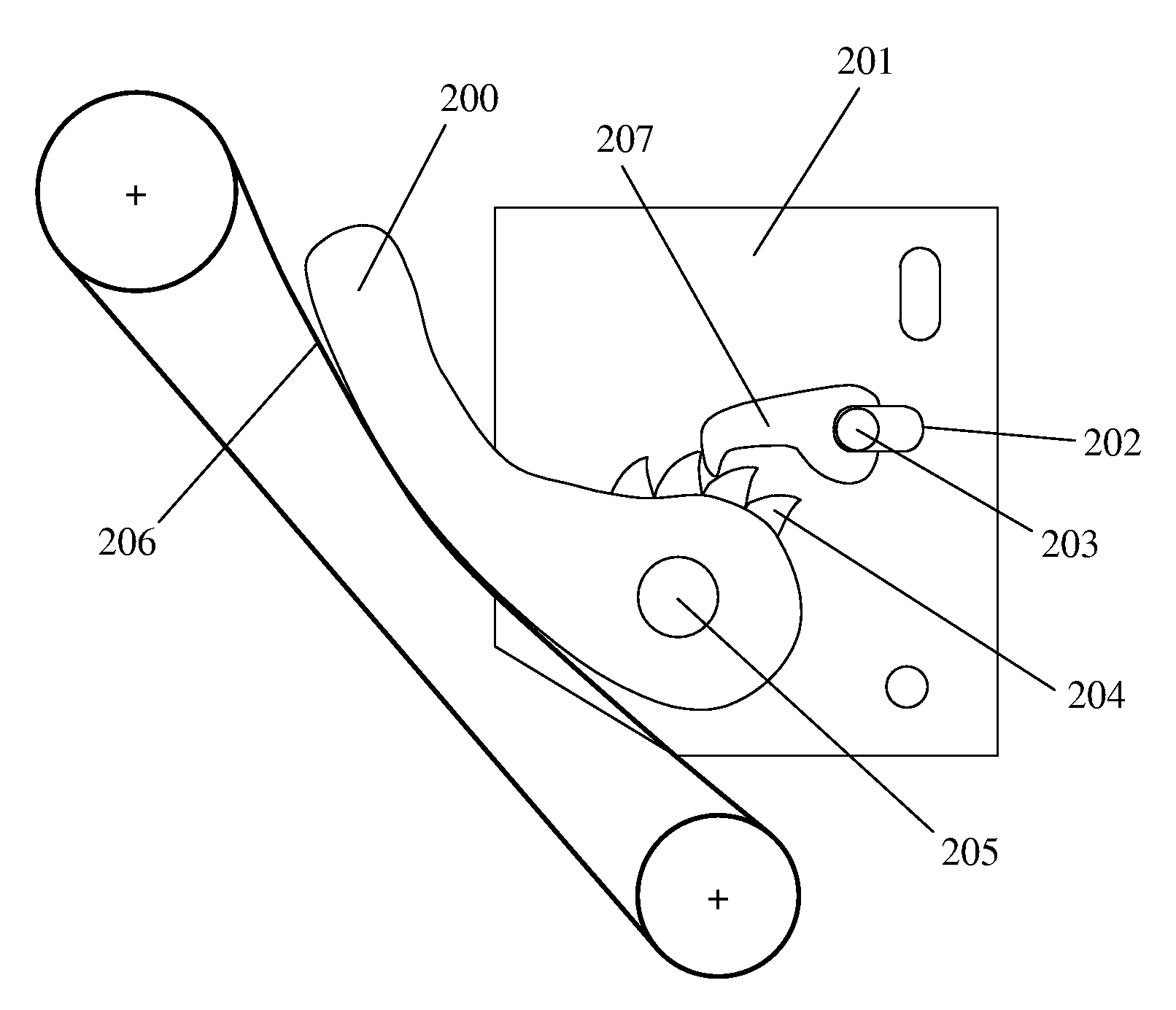
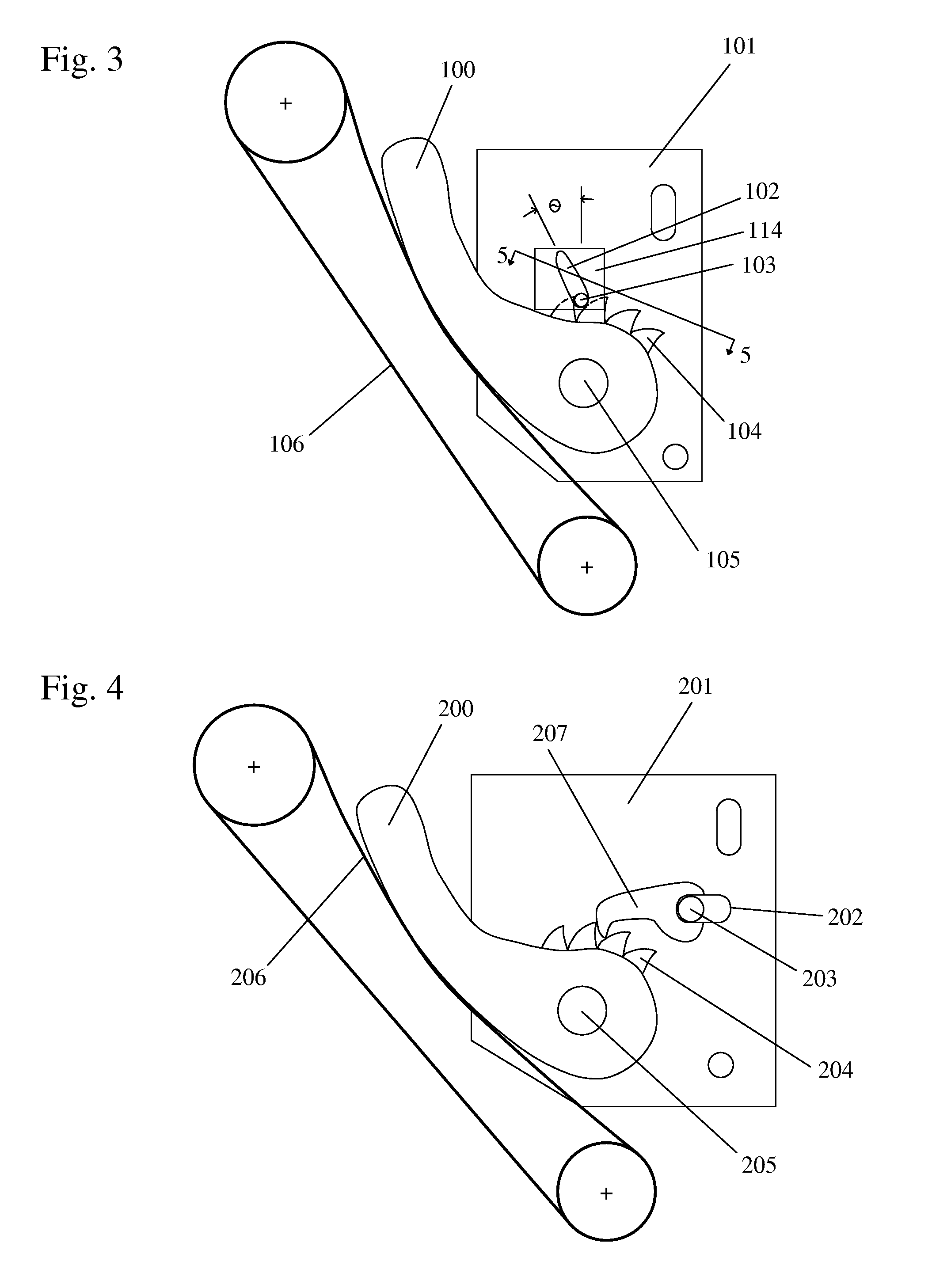
[0023]An engine chain or belt tensioning system of the present invention includes a tensioner pivot arm with a ratcheting means that includes backlash (backdrive) in an engine timing system. The tensioner system includes a tensioner pivot arm having a fixed pivot pin and radially projecting ratchet teeth affixed to the tensioner pivot arm. In one embodiment, the tensioner arm is preferably made of plastic. The pivot arm is biased by a tensioner pivot arm biasing device. The pivot arm biasing device is preferably a spring, including, but not limited to, a torsional spring, a compression spring, or a tension spring. Alternatively, the pivot arm biasing device is a hydraulic piston. An engagement mechanism, such as a pin or ball, engages the radially projecting ratchet teeth. A bracket slidably contains the pin or ball, and a biasing force, either mechanical or gravitational, biases the pin or ball. Some examples for the biasing force include, but are not limited to, a torsion spring, ...


PUM


Abstract

An engine chain or belt tensioning system includes a tensioner pivot arm with a ratcheting means that includes backlash in an engine timing system. The tensioner system includes a tensioner pivot arm having a fixed pin, radially projecting ratchet teeth, a tensioner pivot arm biasing device, and a ratchet mechanism that engages the radially projecting ratchet teeth. The ratchet mechanism is oriented such that the tensioner pivot arm freely rotates in one direction, but backdrive is limited in the opposite direction.

Description

REFERENCE TO RELATED APPLICATIONS[0001]This application claims one or more inventions which were disclosed in Provisional Application No. 60 / 862,780, filed Oct. 25, 2006, entitled “PIVOT ARM TENSIONER WITH SLIDING RATCHET MECHANISM”. The benefit under 35 USC §119(e) of the United States provisional application is hereby claimed, and the aforementioned application is hereby incorporated herein by reference.BACKGROUND OF THE INVENTION[0002]1. Field of the Invention[0003]The present invention relates generally to tensioners used with chain drives in automotive timing and power transmission applications. In particular, the present invention is related to a ratcheting tensioner system.[0004]2. Description of Related Art[0005]A tensioning device, such as a mechanical tensioner, is used as a control device for a power transmission chain, or similar power transmission devices, as the chain travels between a plurality of sprockets. In this device, the chain transmits power from a driving spr...

Claims


Application Information

Patent Timeline
IPC IPC(8): F16H7/08
CPCF16H7/0848F16H2007/0893F16H2007/0853F16H7/18F16H7/08
Inventor CHEKANSKY, JASON W.
Owner BORGWARNER INC
Why Eureka
Try Eureka