
Operatively tuning implants for increased performance

a technology for tuning implants and implants, applied in the field of optimizing implant positions, can solve the problems of poor post-operative patient outcomes, high probability of revision knee surgery due to pain or abnormal wear, and prior art software that fine-tunes the anatomical placement of implants, etc., and achieves good postoperative biomechanic function, good intra-operative ligament balance, and good anatomic fi

Active Publication Date: 2010-03-25
SMITH & NEPHEW INC
View PDF78 Cites 522 Cited by
  • Summary
  • Abstract
  • Description
  • Claims
  • Application Information

AI Technical Summary

Benefits of technology

[0012]Also, where used herein, the term “anatomic fit” broadly encompasses considerations of: 1) resection efficiency (i.e., minimizing bone loss for the patient given a particular prosthesis geometry), 2) interface fit (i.e., how well the prosthesis adheres to bone and how robust the prosthesis is to cement interface shear loading given a large range of spatial orientations and / or bone interface geometries), and 3) bone coverage / fit (i.e., how well the prosthesis covers bone without overhanging or under-hanging which could cause soft-tissue impingement)
[0018]The present invention serves to increase functional performance (e.g., biomechanic function), increase durability (e.g., reduce wear), reduce or eliminate abnormal motion (e.g., paradoxical motion), and create a more natural postoperative feeling (e.g., improved proprioception) for said individual patient. By measuring, interpreting, and understanding the preoperative biomechanic characteristics of a patient's knee or other joint, computer simulation models can assist a surgeon by providing one or more suggested surgical plans along with expected performance results corresponding to each of said one or more suggested surgical plans. Such surgical plans may generally provide suggestions for optimizing implant sizing, varus / valgus cut angle, posterior slope cut angle, internal / external rotational positioning angle, cut depth, anterior / posterior cut locations, flexion / extension cut angle, and medial / lateral positioning of a selected prosthesis so as to optimize ligamentous or other soft tissue releases. The computer simulation models may further assist the surgeon in selecting one or more proper prosthetic components from any given number of standard or custom prosthesis designs from one or more orthopedic manufacturers.
[0019]It is anticipated that by utilizing the method steps provided by the present invention, final positioning of a knee prosthesis within the patient's joint is optimized to reduce quadriceps misfire and strain, reduce implant loosening and subluxation, maintain balanced soft-tissue envelopes, reduce implant wear (by positioning implant components in such a way that magnitudes and directions of frictional forces experienced during a patient's typical biomechanic functions are minimized), reduce or eliminate abnormal motion, and give the patient a more natural postoperative feeling.
[0020]FIG. 13 is a Venn diagram (800) illustrating problems encountered by prior art surgical methods. The diagram (800) comprises at least three prosthetic performance circles (802, 804, and 806). Performance circle (802) is representative of best anatomic fit for a given prosthesis. Ligament balance performance circle (804) is representative of best intra-operative ligament balancing that can be achieved without patient muscle input and other dynamic input. For instance, a good flexion / extension gap and good stability during trial reduction in TKA might place an overall prosthesis performance value (812) within the ligament balance performance circle (804).
[0024]It is therefore a goal of the present invention to help a surgeon determine how to implant one or more prosthetic components of a prosthesis in order to get the best overall anatomic fit (802), intra-operative ligament balance (804), and postoperative biomechanic performance (806) simultaneously, as indicated by the overall prosthesis performance value (814). Overall prosthesis performance value (814) is exemplary of a prosthetic configuration which is sized and spatially oriented so that it achieves good anatomic fit (802), as well aso provides good intra-operative ligament balance (804) and good postoperative biomechanic function (804) during dynamic activities routinely performed by the patient.
[0025]It is also a goal of the present invention to enable a surgeon to make the best possible compromises between anatomic fit (802), intra-operative ligament balance (804), and postoperative biomechanic function (806) in situations when all three performance characteristics (802, 804, 806) cannot be achieved simultaneously. For instance, for some prosthetic implants, computer simulations may indicate that good biomechanic performance (806″) will not yield good anatomic fit (802). In such instances, the surgeon may have to give up some biomechanic performance (806″) for better anatomic fit (802), or select a different prosthetic implant which is more robust and / or suitable for the patient.

Problems solved by technology

While these programs have been used to design implant geometries in the past, the prior art has not utilized such software to fine-tune the anatomical placement of implants (i.e., standard and custom) so that they meet and exceed an individual patient's needs.
Many times in total knee arthroplasty (TKA), poor post-operative patient outcomes are not caused from a poorly-designed prosthesis.
Instead, the problem may often stem from a well-designed prosthesis being installed in a less-than-optimal biomechanic position relative to the natural anatomy of the patient in an attempt to get the best anatomic fit.
In other words, the probability of revision knee surgery due to pain or abnormal wear may be high even with a well-designed knee-prosthesis, if said prosthesis is misaligned or if said prosthesis is installed without considering the biomechanic effects of prosthetic orientation.

Method used


Image

  • Operatively tuning implants for increased performance
  • Operatively tuning implants for increased performance
  • Operatively tuning implants for increased performance

Examples


examples

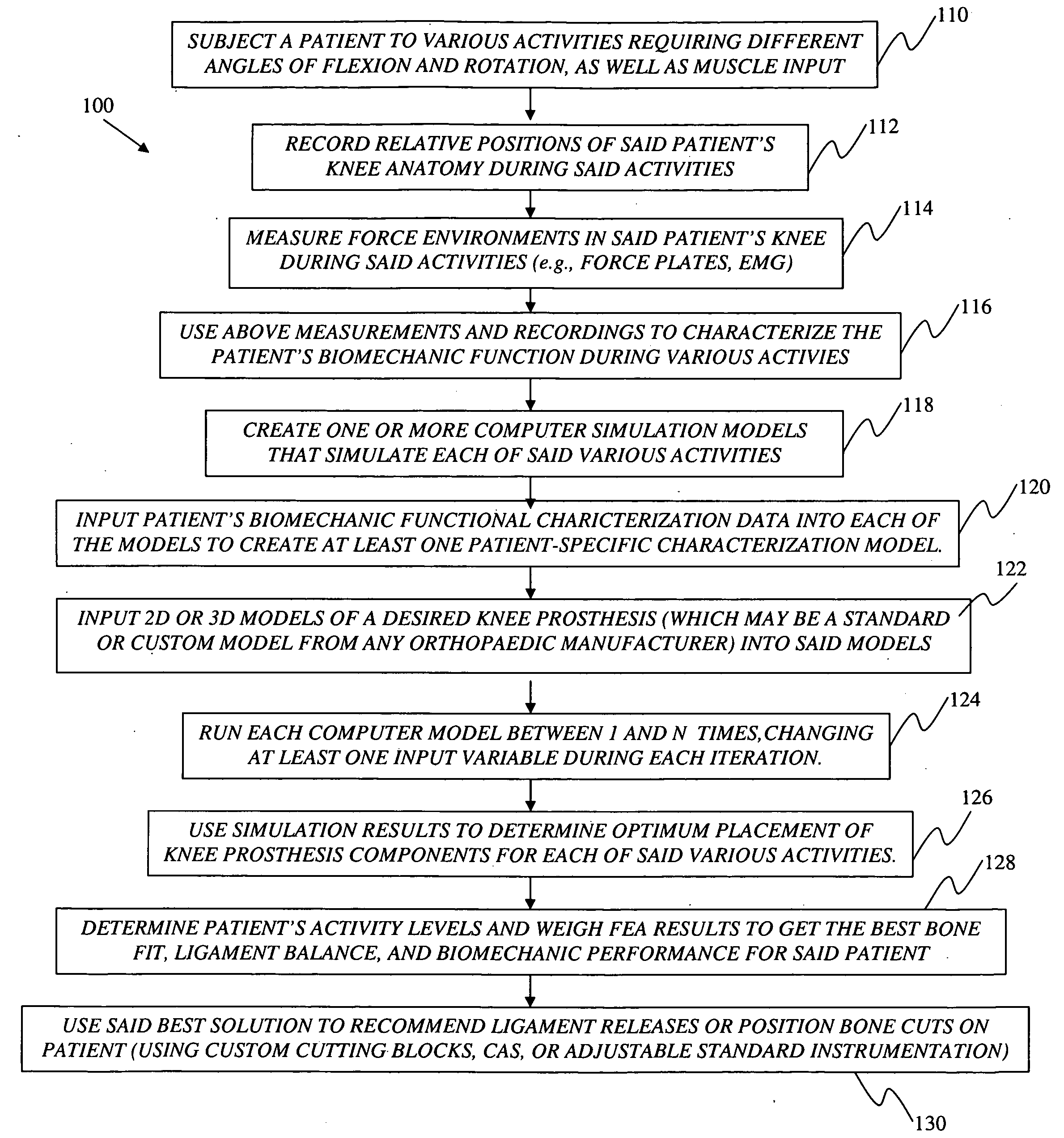
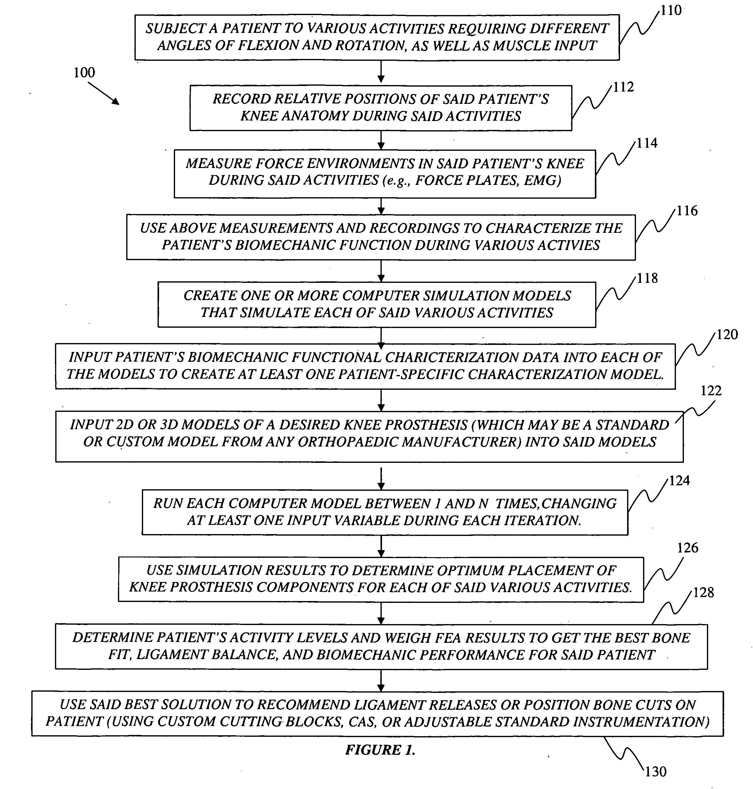
[0112]In a first example of the present invention, a candidate for knee surgery who enjoys running will be measured while performing several various activities with an emphasis on uphill, downhill, and level jogging. The candidate's functional characterization may be determined by performing said activities on a treadmill or inclined force plate while jogging in place. It may be determined through steps (110), (112), and (114) that said candidate generally tends to have more external rotation in full extension than is normal (i.e., the patient has an out-toeing abnormality). In this instance, iterative model simulation may be used to characterize and analyze the patient's jog on the computer with a virtually-implanted Smith & Nephew Legion™ Primary system. The simulation results might indicate that the tibial component should be positioned with slightly greater posterior slope than normal, so as to give the patient more postoperative AP stability (tibial drawer test), since this ori...


PUM


Abstract

A method for preoperatively characterizing an individual patient's biomechanic function in preparation of implanting a prosthesis is provided. The method includes subjecting a patient to various activities, recording relative positions of anatomy during said various activities, measuring force environments responsive to said patient's anatomy and affected area during said various activities, characterizing the patient's biomechanic function from said relative positions and corresponding force environments, inputting the measured force environments, relative positions of knee anatomy, and patient's biomechanic function characterization into one or more computer simulation models, inputting a computer model of the prosthesis into said one or more computer simulation models, and manipulating the placement of the prosthesis in the computer simulation using said patient's biomechanic function characterization and said computer model of the prosthesis to approximate a preferred biomechanical fit of the prosthesis.

Description

CROSS-REFERENCE TO RELATED APPLICATIONS[0001]N / ABACKGROUND OF THE INVENTION[0002]1. Field of the Invention[0003]The present invention relates generally to optimizing implant position during total knee arthroplasty (TKA), and more particularly to a novel method of preoperatively characterizing an individual patient's biomechanic function in order to optimize the orientation of components of a knee prosthesis.[0004]2. Related Art[0005]Software programs which simulate in-vivo functional activities (e.g., LifeMOD™ / KneeSIM, a product of LifeModeler®, Inc. San Clemente, Calif.), have been used for the purpose of evaluating the performance of implant designs. Such programs use a three-dimensional, dynamics-oriented, physics-based modeling methodology. While these programs have been used to design implant geometries in the past, the prior art has not utilized such software to fine-tune the anatomical placement of implants (i.e., standard and custom) so that they meet and exceed an individua...

Claims


Application Information

Patent Timeline
IPC IPC(8): A61F2/38A61B5/103G16B5/00
CPCA61B5/103A61B5/4528A61B5/4533A61B5/4824A61F2/38G06F19/12A61F2002/30955A61F2002/3096G06F19/3437G06F19/3481A61B5/6878A61F2002/30945G16H50/50B33Y80/00B33Y50/00G16B5/00A61F2002/30943G16H30/20G16H20/30G16H20/40A61B34/10A61B2034/108
Inventor OTTO, JASON KARLMCKINNON, BRIAN W.NADZADI, MARK ELLSWORTH
Owner SMITH & NEPHEW INC
Learn More