
Coaxial gear set

Active Publication Date: 2010-04-01
WITTENSTEIN SE
View PDF3 Cites 18 Cited by
  • Summary
  • Abstract
  • Description
  • Claims
  • Application Information

AI Technical Summary

Benefits of technology

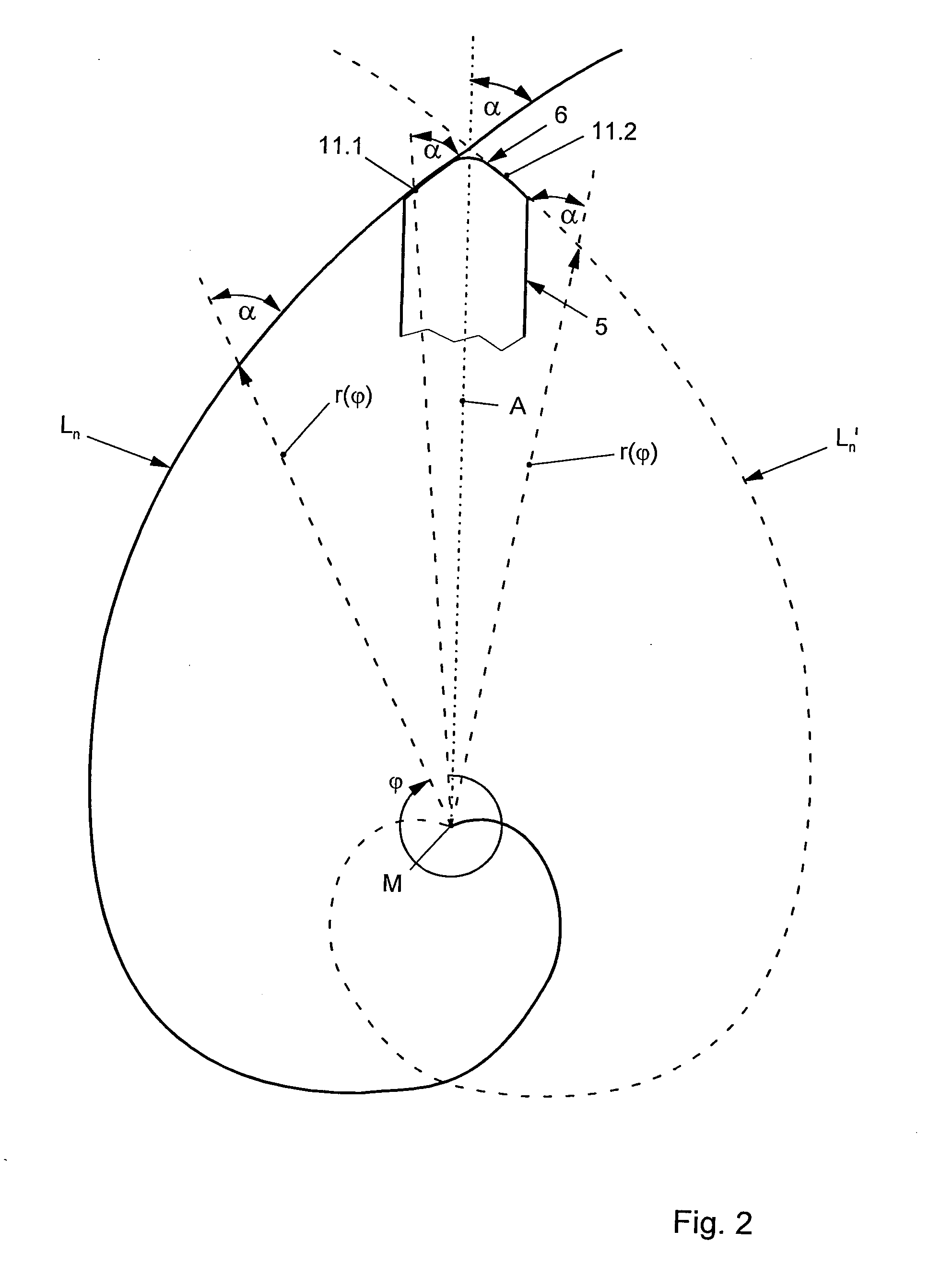
[0011]The geometry of the logarithmic spiral with full surface contact during the radial movement of the tooth segment into the internal toothing system of the internal gear ensures an optimum load distribution (pressure distribution), with the result that an optimum transmission of high moments is possible with wear which is as low as possible and, in particular, uniform.
[0012]As a result, the service life of a coaxial gear set of this type can be increased substantially, it being possible at the same time for very high moments to be transmitted. This ensures surface contact independently of the radius and size of the gear set.
[0013]Here, an angle α can be selected freely between 5°and 85°, preferably between 15° and 45°, by the corresponding function of the logarithmic spiral, with the result that different tooth flank geometries of the internal toothing system and of the tooth segments can also be influenced.
[0014]Independently of the radius, in the selection of a defined logarithmic spiral, coaxial gear sets of different size can then accordingly be produced with different diameters, in which one and the same tooth segment can be used. This is likewise a great advantage, since one and the same tooth segment can be used for coaxial gear sets of different size.
[0015]The adaptation of a correspondingly curved internal gear root fillet to the tip curve of the tooth segment can influence a jolt-free positively guided pushing back of the tooth segment if the latter runs through the tooth root of the internal toothing system of the internal gear. This provides a jolt-free transition between an up and down movement of the tooth segments.

Problems solved by technology

It is a disadvantage of this that force and moments are transmitted merely via the linear contact.
As a result of this rolling linear contact between a tooth flank contour of the tooth segment and a contour of an internal toothing system of the internal gear, a high loading (pressing) with high wear is set, in particular in the case of very high forces.

Method used


Image

  • Coaxial gear set
  • Coaxial gear set
  • Coaxial gear set

Examples


Embodiment Construction

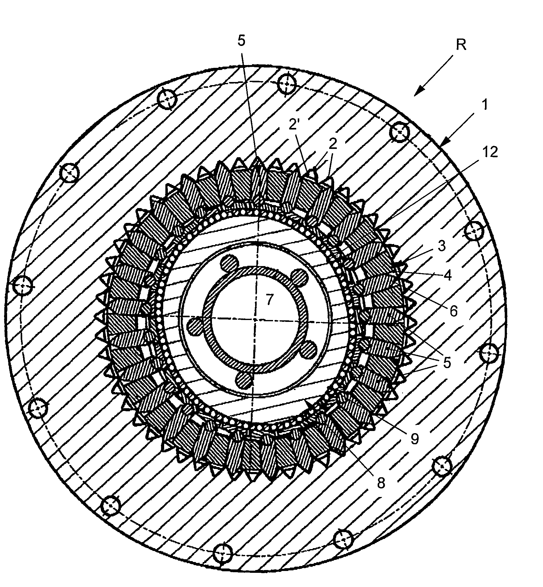
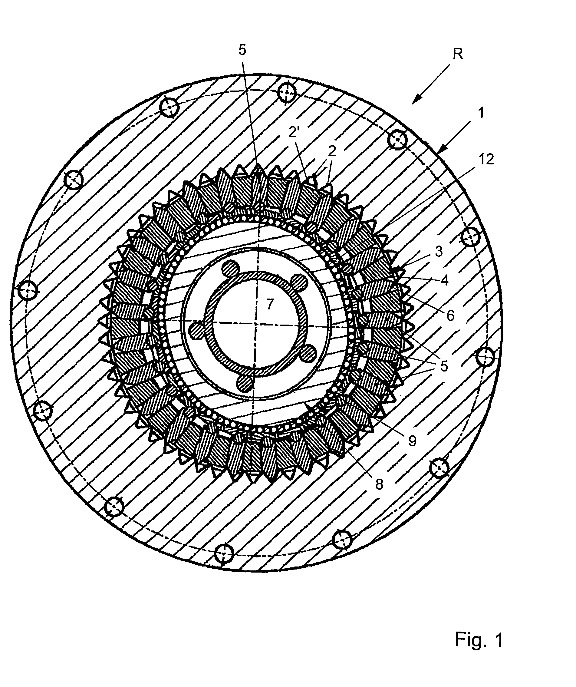
[0020]According to FIG. 1, a coaxial gear set R has an internal gear 1 which has a toothing system 2 which lies on the inside. An element 3, preferably configured as an output element, is inserted in a circularly annular manner within the internal gear 1, a plurality of tooth segments 5 which are inserted radially next to one another and into corresponding guides 4 being arranged in the circularly annular element 3. The tooth segments 5 are mounted such that they can be displaced radially to and fro within the guide 4 and have a tooth contour 6 or tooth flank contour at one end.

[0021]A drive element 7, configured as a shaft or as a hollow shaft, is provided within the element 3 with received tooth segments 5, which drive element 7 has an outer profiling 8 which can be of polygonal or lug-like configuration, for example with a contour 9, as an elevation.

[0022]A bearing (not shown in more detail here) is likewise provided between the outer contour 9 of the profiling 8 of the drive ele...


PUM


Abstract

A coaxial gear set, in particular a hollow shaft gear set for industrial drive technology, having high power density, comprising a drive element (7), an element (3), and an output element, with a gear ratio and a transmission of a drive torque occurring between the drive element (7) and the output element via a plurality of radially movable tooth segments (5), an outer tooth flank contour (11.1, 11.2) of the tooth contour (6) of the tooth segments (5) and / or a flank contour (12.1, 12.2) of a gearing (13) of an inner gearing (15) of an internal wheel (1), relative to a gear axis (M), a tooth contour that allows surface contact in the engagement area comprising a logarithmic spiral.

Description

BACKGROUND OF THE INVENTION[0001]The present invention relates to a coaxial gear set, in particular a hollow shaft gear set for industrial drive technology with a high power density, having a drive element, an element and an output element, a step-up ratio and a transmission of a drive moment taking place between the drive element and the output element via a plurality of radially movable tooth segments.[0002]Conventional gear sets are known and customary in the marketplace in a wide variety of forms and embodiments. In a coaxial gear set, substantially a tooth segment is moved into an internal toothing system of an internal gear via a drive element which is provided with a contour, in order to produce a step-up ratio and to transmit a moment.[0003]Here, the conventional symmetries between the tooth flanks of the tooth segment and the tooth geometry of the internal toothing system of an internal gear are selected in such a way that the tooth flanks of the tooth segments make contact...

Claims


Application Information

Patent Timeline
IPC IPC(8): F16H37/04
CPCF16H25/06F16H49/001F16H2055/0893Y10T74/18024Y10T74/19Y10T74/1836Y10T74/19972Y10T74/19967
Inventor SCHREIBER, HEIKO
Owner WITTENSTEIN SE
Learn More