Pneumatic Tire

a technology of pneumatic tires and tyres, applied in the field of pneumatic tires, can solve the problems of short circuit generation, radio noise, adverse influence of electronic circuit parts, etc., and achieve the effect of eliminating problems, excellent rolling resistance and wet properties

Active Publication Date: 2010-04-01
TOYO TIRE & RUBBER CO LTD
View PDF26 Cites 26 Cited by
  • Summary
  • Abstract
  • Description
  • Claims
  • Application Information

AI Technical Summary

Benefits of technology

[0017]By forming a conductive path reaching a wing from a rim strip by utilizing a conductive carcass ply, the pneumatic tire of the present invention can provide a tire having conductivity while having excellent rolling resistance and wet properties due to silica compounding, that can be manufactured by the conventional process without requiri

Problems solved by technology

With this silica compounding technology, static electricity charged in vehicles gives rise to the problems that discharge phenomenon is generated when a

Method used


Image

  • Pneumatic Tire
  • Pneumatic Tire
  • Pneumatic Tire

Examples


first embodiment

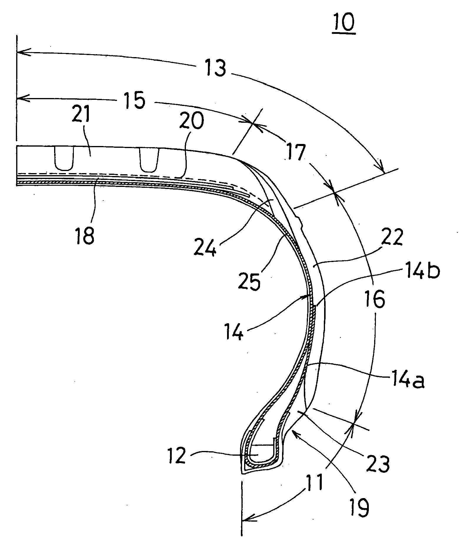
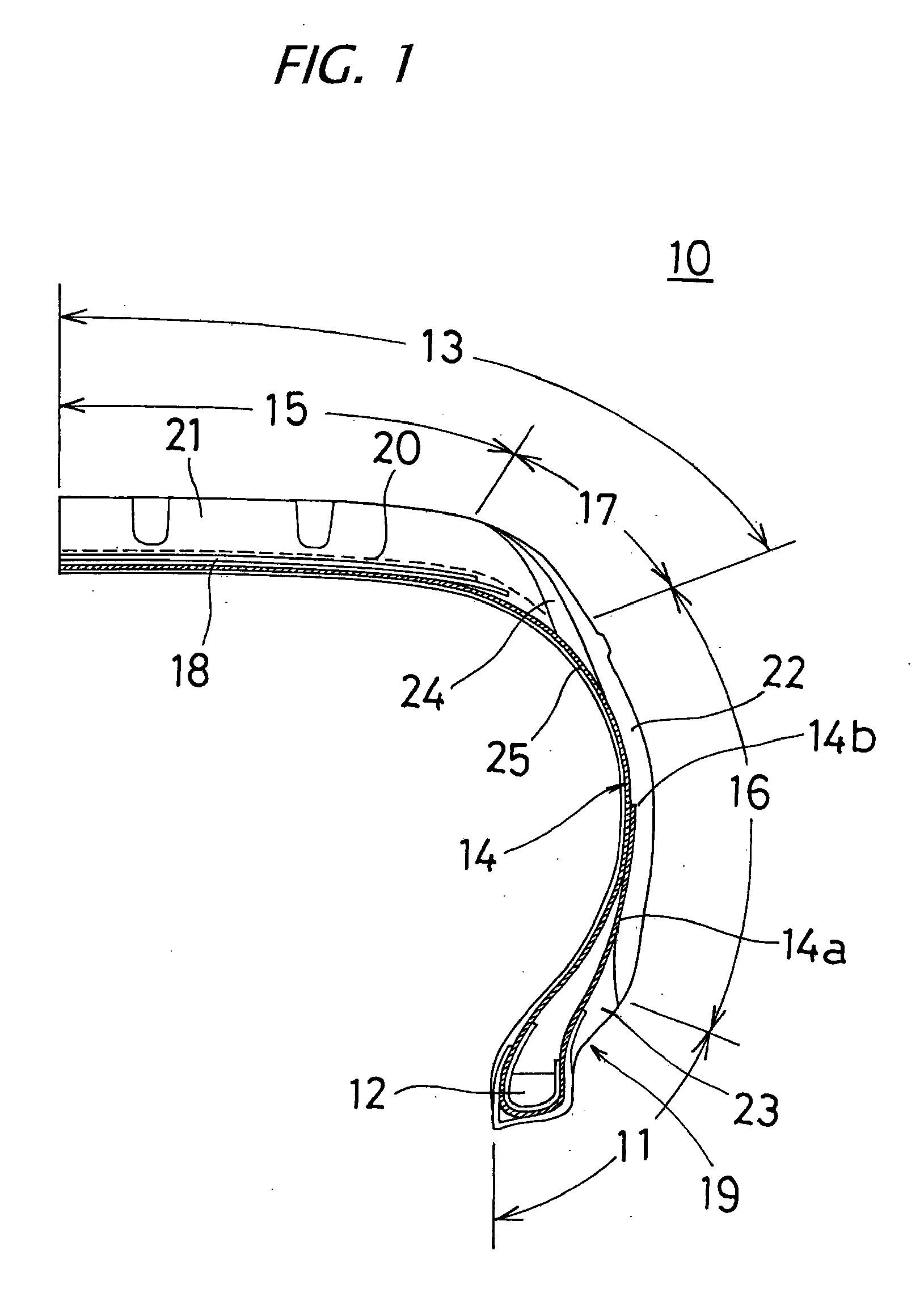
[0019]FIG. 1 is a semi-sectional view showing a pneumatic tire 10 of a first embodiment of the invention.

[0020]The pneumatic tire (hereinafter, the pneumatic tire is simply referred to as a “tire”) 10 comprises a carcass 14 comprising one carcass ply 25 which is turned back from the inside of the tire to the outside thereof around a bead core 12 embedded in each of a pair of the bead parts 11, and locked, a tread part 13 located at an outer circumferential side in a radial direction of the tire of the carcass 14, a side wall part 16 located at the side part of the carcass 14, and a belt 18 comprising two crossed belt plies provided inward the tread part 13 and between the tread part 13 and the carcass 14.

[0021]The tire 10 has a rim strip 19 provided outward in an axial direction of the tire of the bead part 11, and the outside face of a rim strip rubber 23 is contacted with a rim, and the inside face thereof is contacted with a turned back portion 14a of the carcass ply 25.

[0022]The...

second embodiment

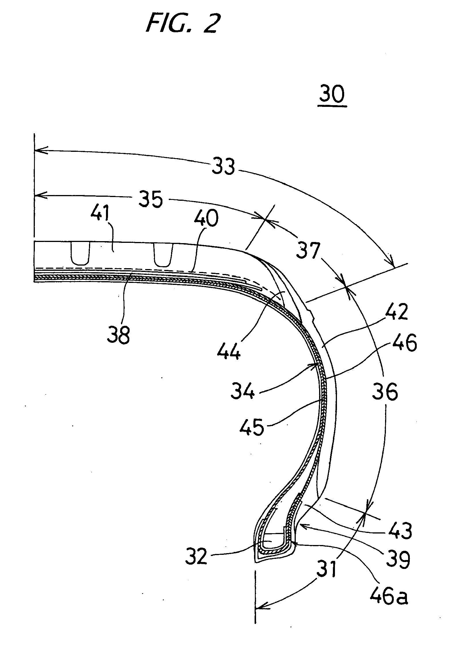
[0064]FIG. 2 is a semi-sectional view showing a pneumatic tire 30 of a second embodiment according to the invention.

[0065]The tire 30 is equipped with two plies carcass 34 comprising two carcass plies 45, 46, a tread part 33 located at the outer circumferential part in a radial direction 5 of the tire of the carcass 34, a side wall part 36 located at the side part of the carcass 34, and a belt 38 comprising two crossed belt plies provided inward the tread part 33 and between the tread part 33 and the carcass 34.

[0066]The tire 30 is that a rim strip 39 is arranged at the outside in an axial direction of the tire of a bead part 31, an outside face of a rim strip rubber 43 is contacted with a rim, and the inside face thereof is contacted with the carcass 34.

[0067]As shown in FIG. 2, the tire 30 has a SWOT structure in which the outside edge in a radial direction of the tire of the side wall part 36 is overlapped on both edges of a crown part 35 constituting a main ground contact part i...

third embodiment

[0088]FIG. 3 is a semi-sectional view showing a pneumatic tire 30 of a third embodiment.

[0089]The tire 50 is equipped with two-ply carcass 54 comprising two carcass plies 65, 66, a tread part 53 located at the outer circumferential side in a radial direction of the tire of the carcass 54, a side wall part 56 located at the side part of the carcass 54, and a belt 58 comprising two crossed belt plies provided inside the tread part 53 and between the tread part 53 and the carcass 54.

[0090]The tire 50 is such that a rim strip 59 is arranged outside in an axial direction of the tire of the bead part 51, an outside face of a rim strip rubber 63 is contacted with a rim, and the inside face thereof is contacted with the carcass 54.

[0091]As shown in FIG. 3, the tire 50 has a SWOT structure in which the outside edge in a radial direction of the tire of the side wall part 56 is overlapped on both edges of a crown part 55 constituting a main ground contact part in the tread part 53. That is, th...


PUM


Abstract

A pneumatic tire that can be manufactured according to the conventional method without requiring special tire manufacturing steps and without needing addition of material members and production steps, and having excellent rolling resistance and wet properties, and having conductivity is to be provided. A pneumatic tire 10 comprises a carcass 14 having a ply which is turned back and locked around a bead core 12, a rim strip 19 provided in a bead part 11, and a wing 24 in which one edge thereof is contacted with the carcass 14 and the other edge is exposed to the surface of a ground contact edge region of a tread part 13, wherein a covering rubber of a carcass ply 25, the rim strip 19 and the wing 24 are formed into a continuous conductive path by a conductive rubber material, only the conductive path is used as a conducting path of the tire 10, and members other than the conducting path are selected and used from a conductive rubber material or a nonconductive rubber material.

Description

TECHNICAL FIELD[0001]The present invention relates to a pneumatic tire. More particularly, the invention relates to a pneumatic tire manufactured by the conventional process, that has a tread of silica compounding or the like, improves rolling resistance and wet properties of a tire, and can discharge static electricity charged in vehicles to road surface.BACKGROUND ART[0002]To improve rolling resistance and running performance (wet properties) on wet road surface of a pneumatic tire, the technology of compounding silica with a rubber composition of a tread as a reinforcing agent in place of the conventional carbon black is known. With this silica compounding technology, static electricity charged in vehicles gives rise to the problems that discharge phenomenon is generated when a tire passes on manholes and the like, resulting in radio noise, adverse influence to electronic circuit parts, generation of short-circuit, and the like.[0003]Conventionally, to solve those problems, the t...

Claims


Application Information

Patent Timeline
IPC IPC(8): B60C19/08
CPCB60C11/01Y10T152/10846B60C19/08Y02T10/86
Inventor NAKAMURA, NORIHIKO
Owner TOYO TIRE & RUBBER CO LTD
Why Eureka
Try Eureka