
Dual-side integrated touch panel structure

a touch panel and integrated technology, applied in the field of touch panel structure, can solve the problems of reducing the use of adhesive layers and extra substrates, and achieve the effect of simplifying the dual-side integrated touch panel structure, reducing the size of the structure, and facilitating operation

Inactive Publication Date: 2010-04-01
J TOUCH CORPORATION
View PDF4 Cites 59 Cited by
  • Summary
  • Abstract
  • Description
  • Claims
  • Application Information

AI Technical Summary

Benefits of technology

[0009]The objective of the present invention is to provide an integrated touch panel structure that combines the advantages of both resistive touch panels and capacitive touch panels. Currently, many electronic devices are designed to be operated on multiple sides, such as mobile phones or PDAs. For foldable mobile phones, the display on the outside is typically used to show messages or other information. For some multi-functional mobile phones, operations such as playing music can be done without flipping open the foldable mobile phone. As more and more functions are built into electronic devices such as mobile phones, a dual-side integrated touch panel structure with the advantages of both resistive touch panel and capacitive touch panel can be very useful in these devices. Because there is a protective layer on the outside of a capacitive touch panel and its sensitivity makes it easy to operate, it is suited for use on the outside of a foldable mobile phone. Other buttons can be placed on the side of the capacitive touch panels. The resistive touch panel can be placed on the inside of the foldable mobile phone for inputting information with the use of a stylus.
[0010]Another objective of the present invention is to provide a simplified dual-side integrated touch panel structure. A lower conductive layer of the resistive touch panel and the conductive layer of the capacitive layer are integrated to be placed on the same substrate. The lower conductive layer of the resistive touch panel is disposed on one side of a transparent polyester or glass substrate, and the conductive layer of the capacitive touch panel is disposed on the other side of the transparent polyester or glass substrate. This reduces the use of an extra adhesive layer and an extra substrate. The structure size is therefore reduced to meet the trend of compact electronic devices.

Problems solved by technology

This reduces the use of an extra adhesive layer and an extra substrate.

Method used


Image

  • Dual-side integrated touch panel structure
  • Dual-side integrated touch panel structure
  • Dual-side integrated touch panel structure

Examples


Embodiment Construction

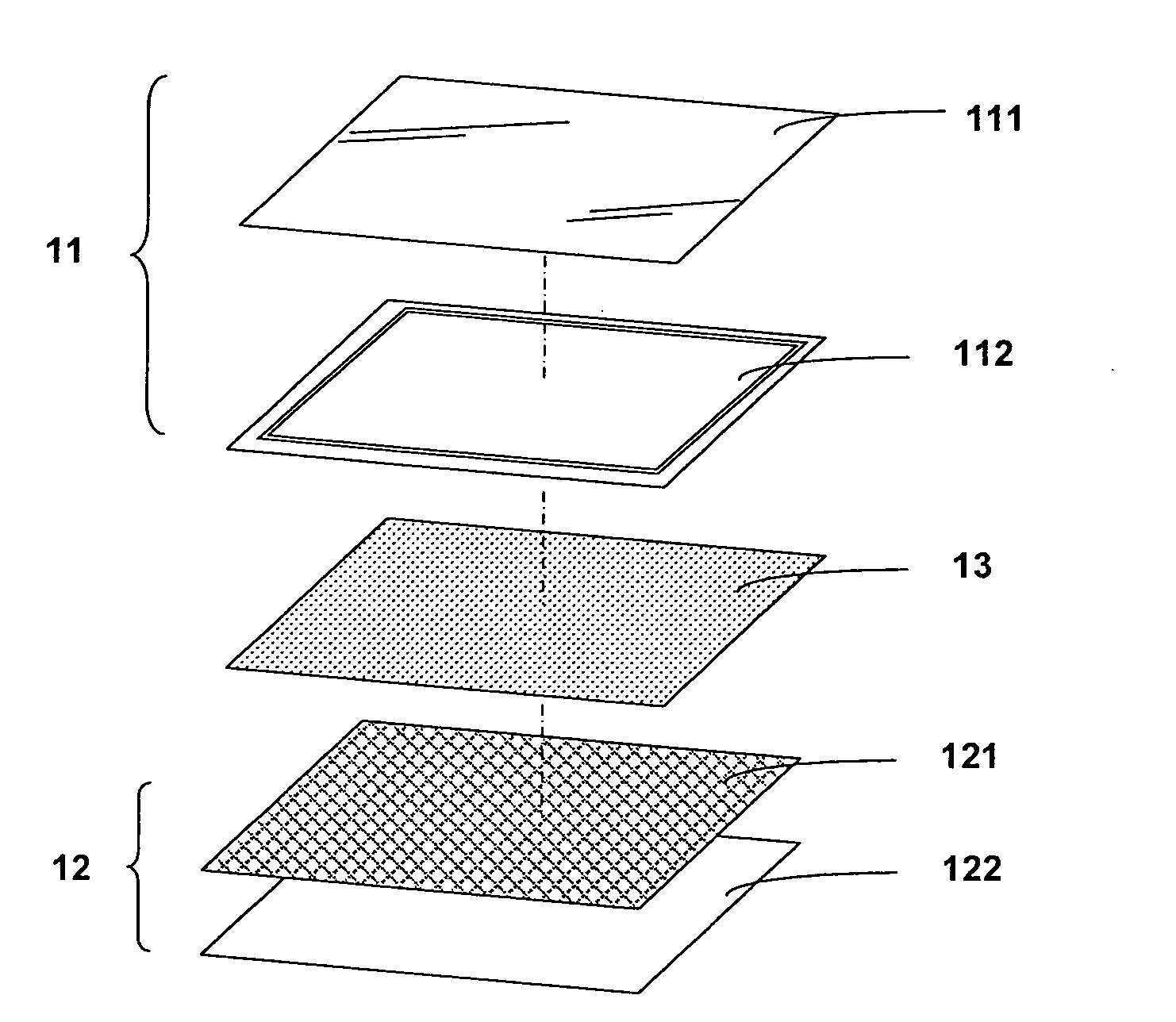
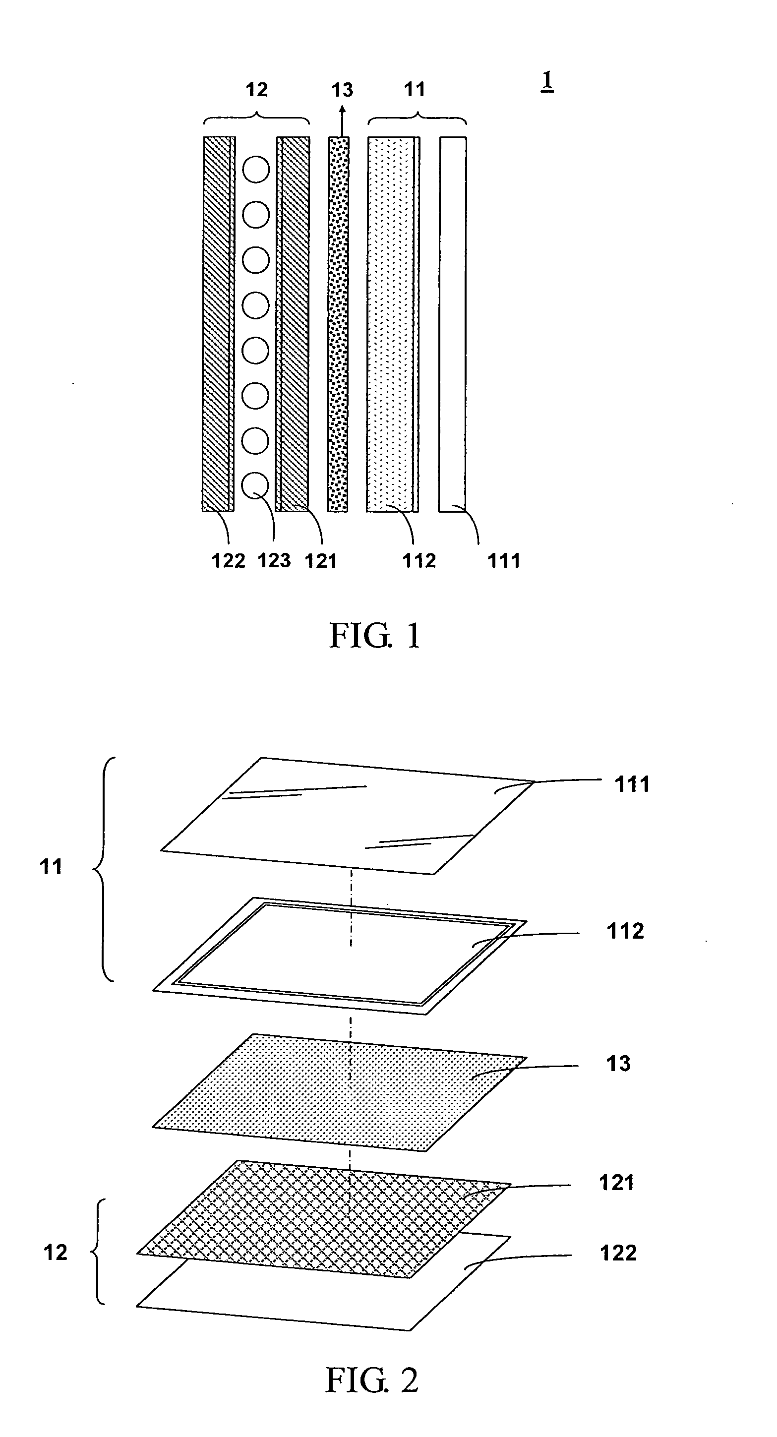
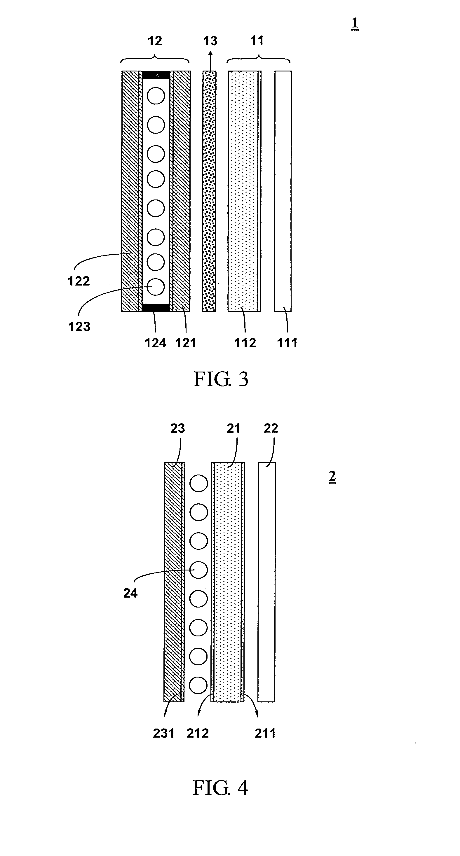
[0019]The present invention relates to a dual-side integrated touch panel structure 1. FIG. 1 and FIG. 2 are the schematic view and the exploded view of the present invention respectively. The structure comprises a first touch panel 11, which is a capacitive touch panel, and a second touch panel 12, which is a resistive touch panel. The backs of the first touch panel and the second touch panel are adhered to each other using an adhesive layer 13. For simplification and clarification purposes, details of touch panels not relating to the present invention are not mentioned in the description and figures. The first touch panel 11 is a capacitive touch panel comprising a protective layer 111 and a conductive layer 112, which is a transparent insulating substrate coated with transparent conductive oxides. The transparent conductive oxides can be indium tin oxide (ITO), antinomy tin oxide (ATO), zinc oxide (ZO), or aluminum doped zinc oxide (AZO). ITO is selected and used in the preferred...


PUM


Abstract

A dual-side integrated touch panel structure is provided. The structure comprises a capacitive touch panel and a resistive touch panel. The backs of the touch panels are adhered together via an adhesive layer so the touch panel structure can be used on two sides and operate two functions. Also, to simplify the structure, conductive layers of different functions are disposed on the two sides of the same substrate. This allows the structure to use one less substrate and one less adhesive layer, and keeps the structure thin.

Description

BACKGROUND OF THE INVENTION[0001]1. Field of the Invention[0002]The present invention relates to a touch panel structure, and more particularly, to a touch panel structure with integrated resistive and capacitive touch panels.[0003]2. Description of the Prior Art[0004]Applications of touch panels have been increasing in recent years. Consumer electronics such as mobile phones, notebook computers, personal digital assistants (PDA), global positioning systems (GPS), ultra mini PCs (UMPC), and MP3 players all have adapted touch panels to improve user interfaces. Resistive and capacitive touch panels are widely used in these applications.[0005]Known resistive touch panel structure comprises an upper ITO conductive layer and a lower ITO conductive layer. Usually, the upper ITO conductive layer is an ITO film and the lower ITO conductive layer is an ITO glass, and the perimeters are printed with silver electrodes for providing electric voltages. The upper conductive layer and the lower co...

Claims


Application Information

Patent Timeline
IPC IPC(8): G06F3/045
CPCG06F3/044H04M2250/16G06F3/045G06F1/1643G06F3/0412G06F3/0443H01B5/14
Inventor YEH, YU-CHOUHO, WEI-HSUAN
Owner J TOUCH CORPORATION
Features
  • Generate Ideas
  • Intellectual Property
  • Life Sciences
  • Materials
  • Tech Scout
  • Unparalleled Data Quality
  • Higher Quality Content
  • 60% Fewer Hallucinations
Learn More