Electric motorcycle

Active Publication Date: 2010-04-01
HONDA MOTOR CO LTD
View PDF2 Cites 24 Cited by
  • Summary
  • Abstract
  • Description
  • Claims
  • Application Information

AI Technical Summary

Benefits of technology

[0007]In view of the situation mentioned above, the present invention is made to provide an electric motorcycle in which disposition space of a motor is downsized, the number of components is reduced, and power transmission efficiency is improved.
[0009]In the present invention, the driving gear is directly coupled to the reduction gear. Therefore, the power generating motor can be disposed close to the rear wheel axle, and the disposition space of the power generating motor can be downsized. Since a conventional pulley provided to a motor shaft of a power generating motor, a conventional pulley provided to a rear wheel axle, and a conventional drive belt coupling each pulley are unnecessary, the number of components can be reduced, and power transmission efficiency can also be improved.
[0014]The driving force can be efficiently transmitted using the minimum number of gears without increasing the number of driving gears because the driving shaft is disposed close to the rear wheel axle. In addition, by driving the rear wheel via the driving gear to match a usage rotation zone of the power generating motor and a speed zone of the vehicle, it also becomes unnecessary to enlarge the power generating motor more than needed.
[0015]In the present invention, a driving shaft of a power generating motor is disposed generally in parallel with a rear wheel axle of a rear wheel. A driving gear is provided on the driving shaft. The driving gear is in meshing engagement with a reduction gear provided on the rear wheel axle. The driving gear has a smaller diameter than that of the reduction gear. A driving force of the power generating motor is transmitted to the rear wheel axle. Accordingly, since the driving gear is directly coupled to the reduction gear, the power generating motor can be disposed close to the rear wheel axle, and the disposition space of the power generating motor can be downsized. Since a conventional pulley provided in a motor shaft of a power generating motor, a conventional pulley provided to a rear wheel axle, and a conventional drive belt connecting each belt pulley are unnecessary, the number of components can be reduced and power transmission efficiency can also be improved.
[0018]A Driving force can be efficiently transmitted using a minimum number of gears without increasing the number of driving gears, because the driving shaft is disposed at the rear end of the swing arm and in the width of the rear wheel in the fore-and-aft direction in planar view and is disposed close to the rear wheel axle. In addition, by driving the rear wheel via the driving gear to match the usage rotation zone of the power generating motor and the speed zone of the vehicle, it also becomes unnecessary to enlarge the power generating motor more than needed.

Problems solved by technology

Therefore, the disposition space of the power generating motor is large.
Since the pulley provided to the motor shaft of the power generating motor, the pulley provided to the rear wheel axle, and the drive belt coupling each pulley are necessary, the number of components is large and power transmission is inefficient.

Method used


Image

  • Electric motorcycle
  • Electric motorcycle
  • Electric motorcycle

Examples


Embodiment Construction

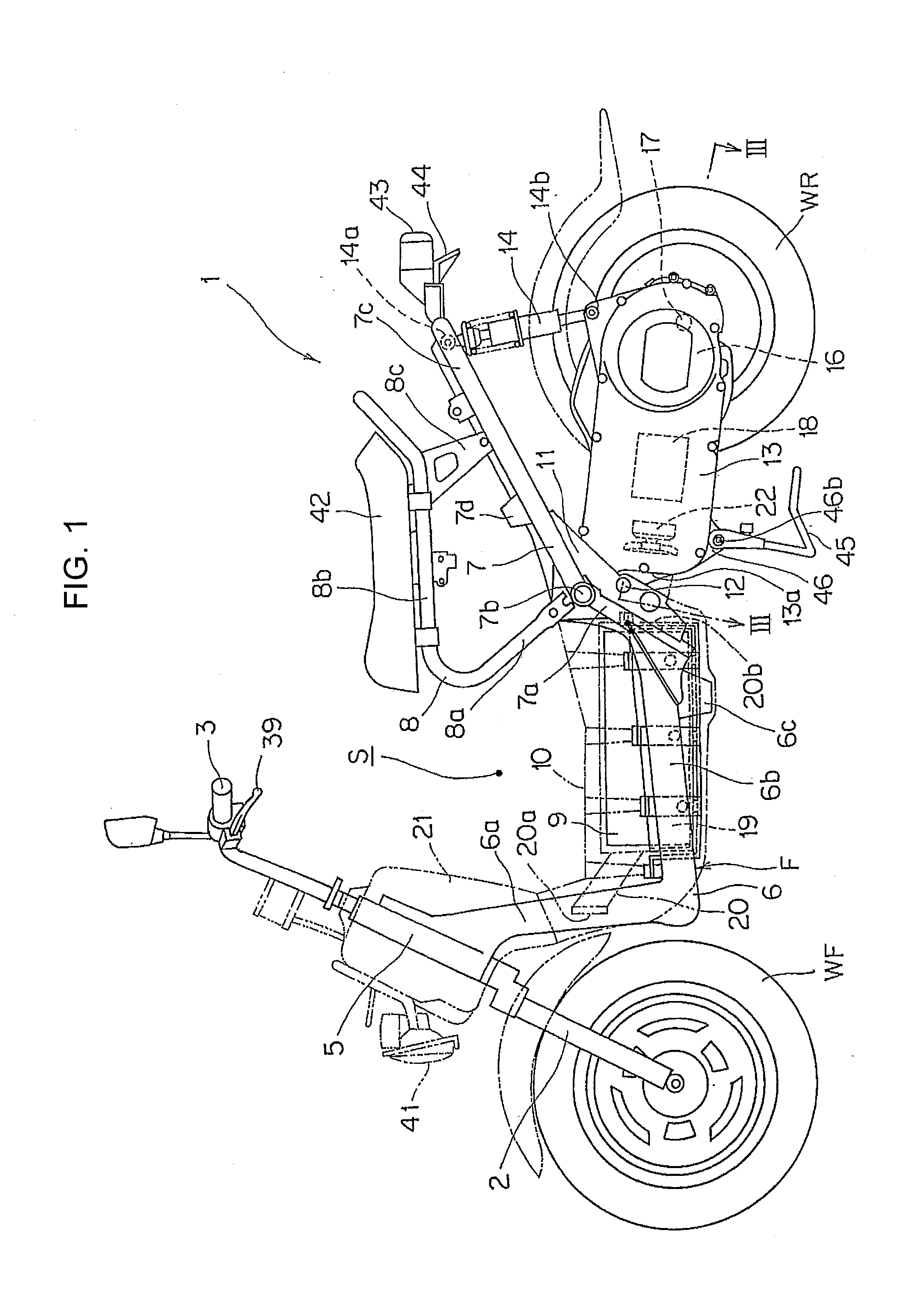
[0032]The present invention will now be described with reference to the accompanying drawings, wherein the same reference numerals have been used to identify the same or similar elements throughout the several views. Vertical, fore-and-aft, and left-and-right directions described in the following explanation are ones seen from a driver.

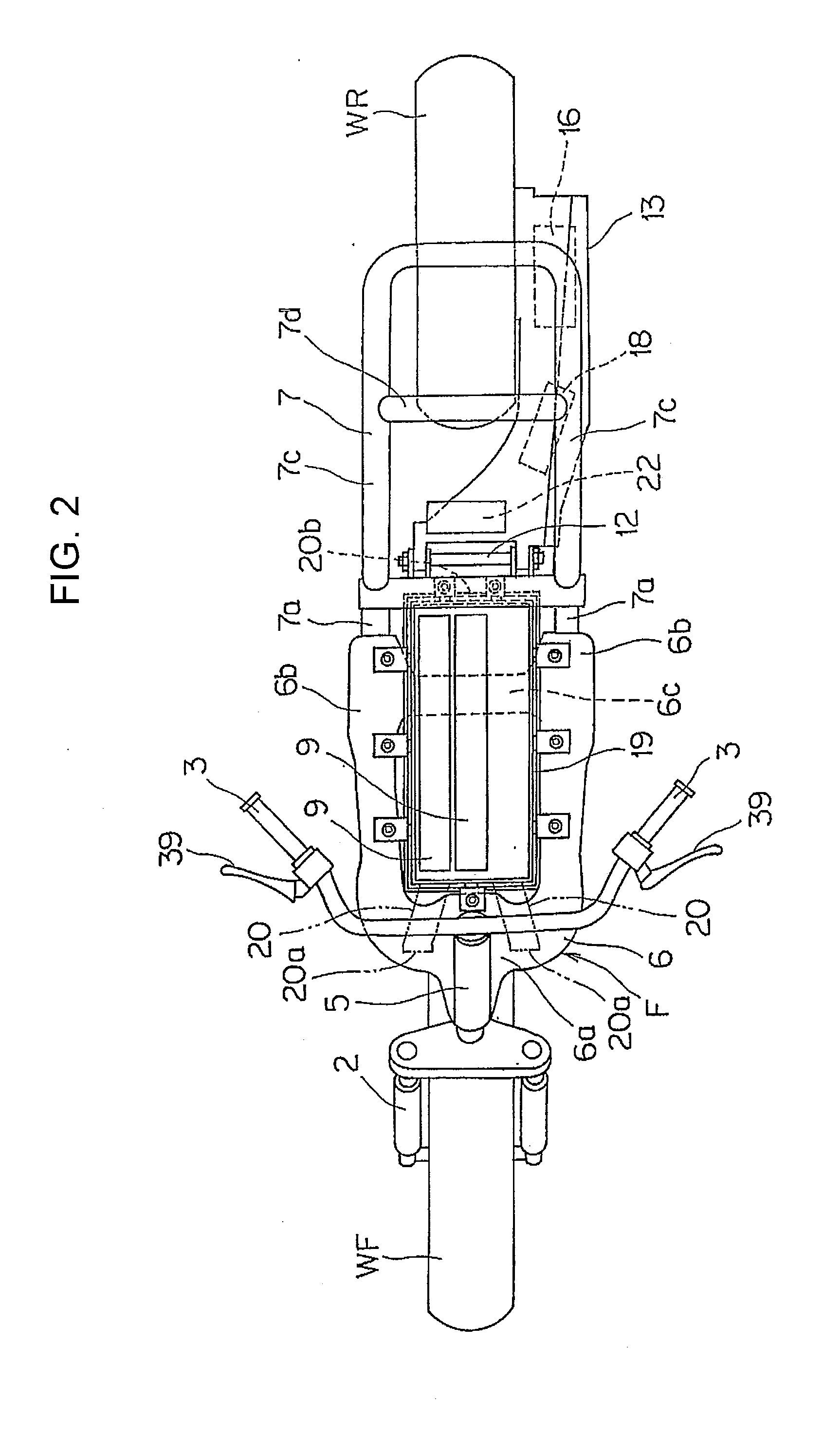
[0033]FIG. 1 is a side view of a battery-driven electric vehicle of an embodiment of the present invention. FIG. 2 is a plane view of the electric vehicle. For ease of explanation, a seat rail 8, a fender cover 21, and a step floor 10 shown in FIG. 1 are not shown in FIG. 2.

[0034]As shown in FIG. 1, a front end of a vehicle body frame F of an electric motorcycle 1 includes: a head pipe 5 which steerably supports a front fork 2 journaling a front wheel WF; and a steering handlebar 3 coupled to the front fork 2. The vehicle body frame F includes a center frame 6, a rear frame 7, and a seat rail 8. As shown in FIG. 2, the frames 6, 7, and 8 are each stru...


PUM


Abstract

An electric motorcycle in which the disposition space of a motor is downsized, the number of components is reduced, and the power transmission efficiency is improved. In an electric motorcycle, a swing arm is swingably supported by a vehicle body frame and supports a power generating motor. A driving shaft of the power generating motor and a rear wheel axle of a rear wheel are coupled together. A driving force of the power generating motor is transmitted to the rear wheel. In the electric motorcycle, the driving shaft of the power generating motor is disposed generally in parallel to the rear wheel axle of the rear wheel. A driving gear is provided on the driving shaft. A driving gear is in meshing engagement with a reduction gear provided on the rear wheel axle. The driving gear has a smaller diameter than that of the reduction gear. A driving force of the power generating motor is transmitted to the rear wheel axle through a reduction.

Description

CROSS-REFERENCE TO RELATED APPLICATIONS[0001]This application claims priority under 35 U.S.C. §119(a) to Application No. 2008-255309, filed in Japan on Sep. 30, 2008, the entirety of which is expressly incorporated herein by reference.BACKGROUND OF THE INVENTION[0002]1. Field of the Invention[0003]The present invention relates to an electric motorcycle driven by a power generating motor.[0004]2. Description of Background Art[0005]In the past, an electric motorcycle carrying a battery, which supplies a power source to drive a power generating motor for traveling, is known. In such an electric motorcycle, a pulley provided to a motor shaft of a power generating motor and a pulley provided to a rear wheel axle are coupled by a drive belt. The driving force of the power generating motor is transmitted to the rear wheel axle via the drive belt (for example, see JP-A No. H4-257783).SUMMARY OF THE INVENTION[0006]However, in the above-mentioned conventional electric motorcycle, the power ge...

Claims


Application Information

Patent Timeline
IPC IPC(8): B62K11/00
CPCB60K7/0007B60K17/043B60K2001/003B60K2007/0038B60K2007/0061B60L2220/46Y02T10/705B62M7/12B60L11/1874B60L11/1877B60L2200/12B60L2220/44Y02T10/7005B62K2204/00B60L50/66B60L58/26Y02T10/70
Inventor KANNO, YOSHIHISAKIKUCHI, HIROYUKI
Owner HONDA MOTOR CO LTD
Why Eureka
Try Eureka