
Process and apparatus for separating solid mixtures

a technology of solid mixture and process, applied in the direction of solid separation, chemistry apparatus and processes, centrifuges, etc., can solve the problems of not being separated, not being able to acceptably high purities by this simple and inexpensive technique, and not being able to achieve acceptable high purities. , the effect of reducing or eliminating the flow ra

Active Publication Date: 2010-04-01
UCHICAGO ARGONNE LLC
View PDF36 Cites 2 Cited by
  • Summary
  • Abstract
  • Description
  • Claims
  • Application Information

AI Technical Summary

Benefits of technology

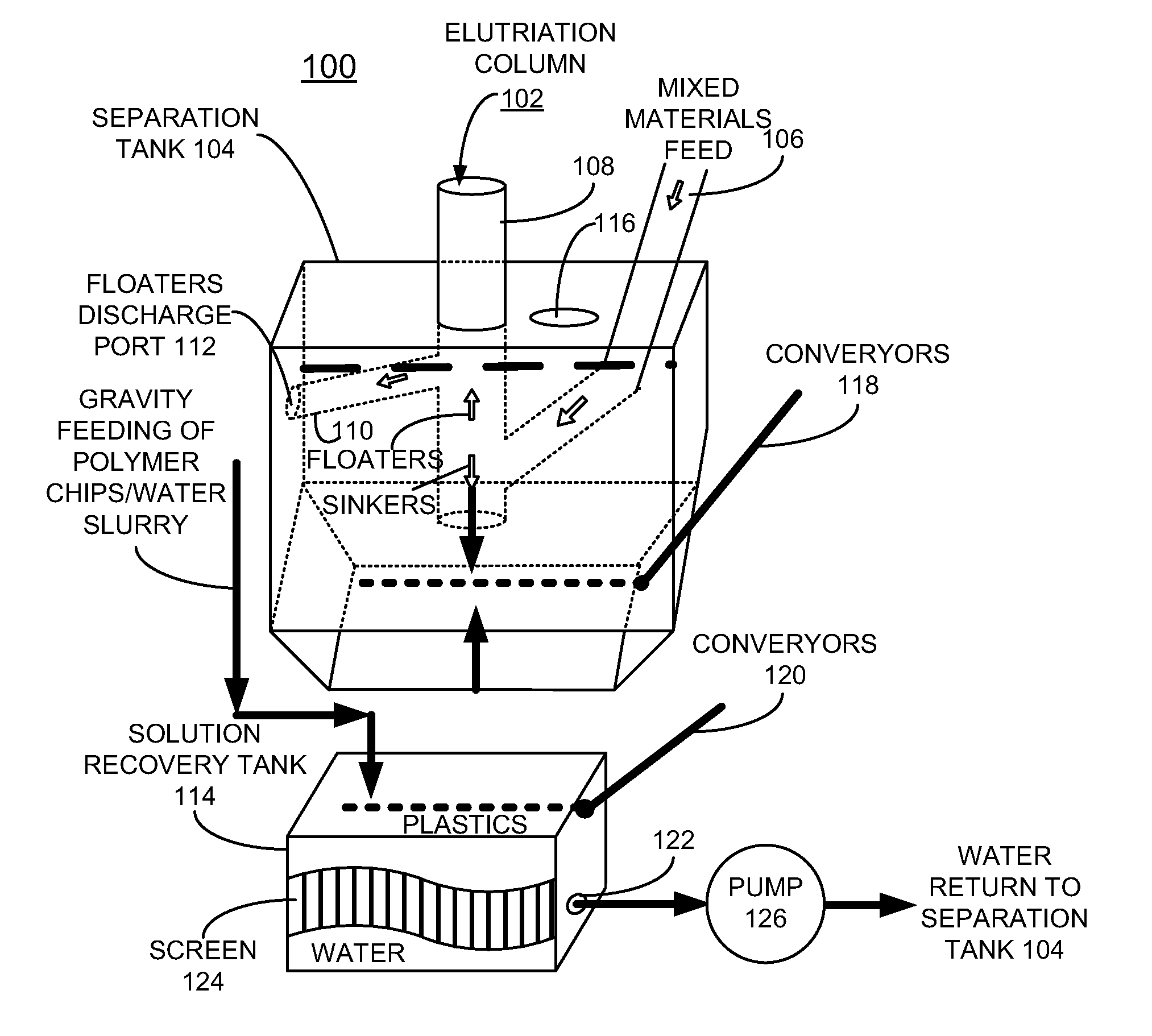
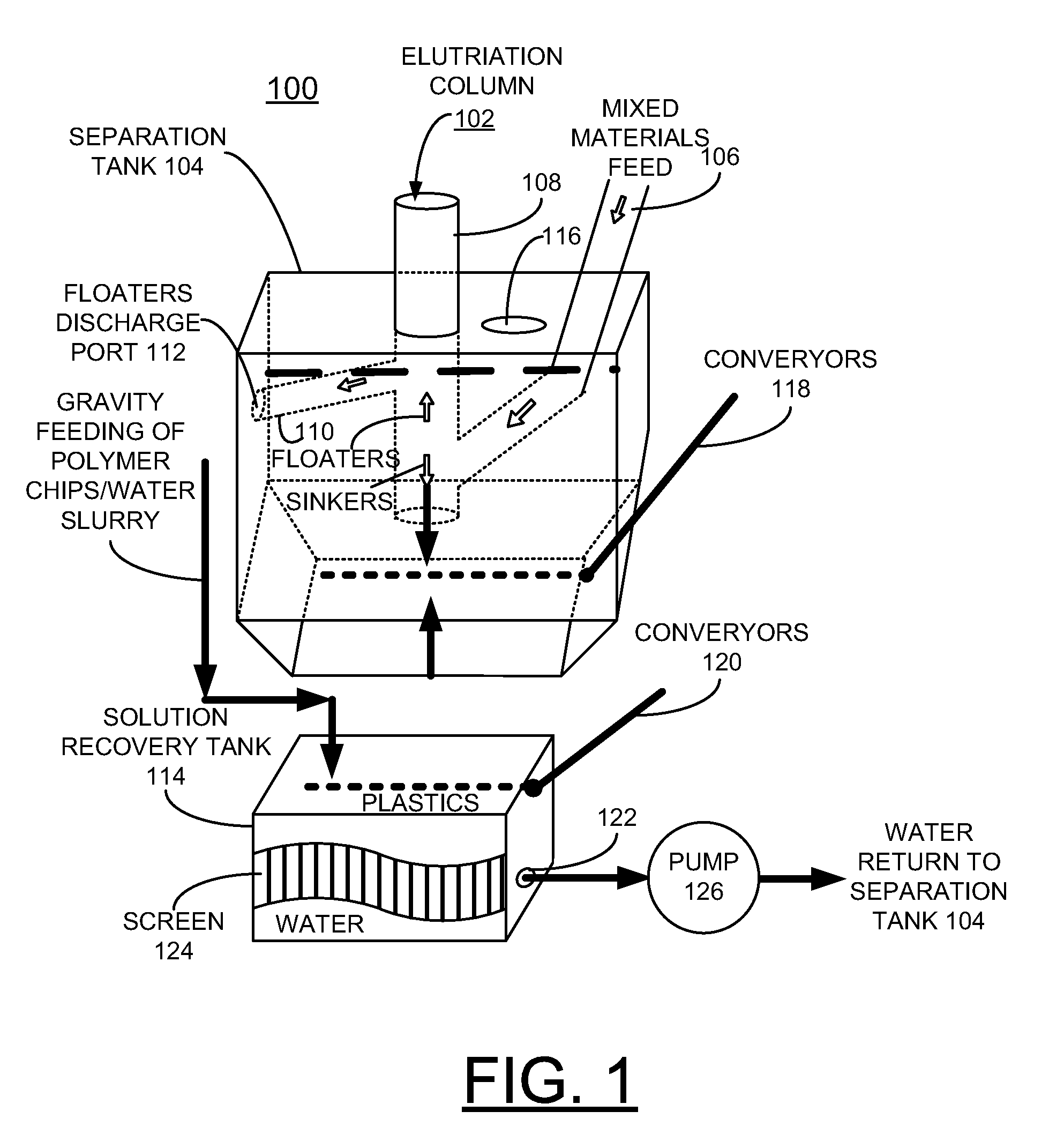
The invention provides an improved process and apparatus for separating solid mixtures using an elutriation column. The process minimizes the need for salts to alter the specific gravity of the solution and the apparatus includes a recovery tank to separate the water from the recovered floater materials. The recovered floater materials are then returned to the separation tank for further processing. The separation tank is sloped at the bottom to accommodate a horizontal screw conveyer and the tank is filled with water and optionally contains a surfactant for some applications. The technical effects of the invention include improved separation efficiency, reduced need for salts, and better handling of heavy materials.

Problems solved by technology

However, materials that have similar or overlapping densities, acrylonitrile butadiene styrene, ABS, and high impact polystyrene, HIPS, cannot be separated in acceptably high purities by this simple and inexpensive technique.
Similarly, wood and various types of rubber materials that are generally found as contaminants in post consumer or post manufacturing waste plastics, have densities that overlap with the densities of the plastics and therefore can not be separated by this technique.
This increases the cost of the process equipment and results in the production of substantial amounts of waste water.

Method used


Image

  • Process and apparatus for separating solid mixtures
  • Process and apparatus for separating solid mixtures
  • Process and apparatus for separating solid mixtures

Examples


Embodiment Construction

[0024]In accordance with features of the invention, an improved process and apparatus are provided for separating solid mixtures. The process minimizes or substantially eliminates the need for chemicals. It should be understood that surfactants may be used for some applications.

[0025]A particle will float in a solution if the net force vector acting on the particle is in the upward direction. This can be achieved by a number of ways. One of these ways is to add salts that dissolve in the solution to increase its density so that it exceeds the density of the particle so that the buoyancy force acting upward on the particle exceeds the gravitational force acting downward on the particle.

[0026]In accordance with features of the invention, a method advantageously is used to set the water or solution in motion at a velocity that can offset the gravitational force acting on the targeted particles in the water or solution so that targeted particles float while the other particles continue ...


PUM


Abstract

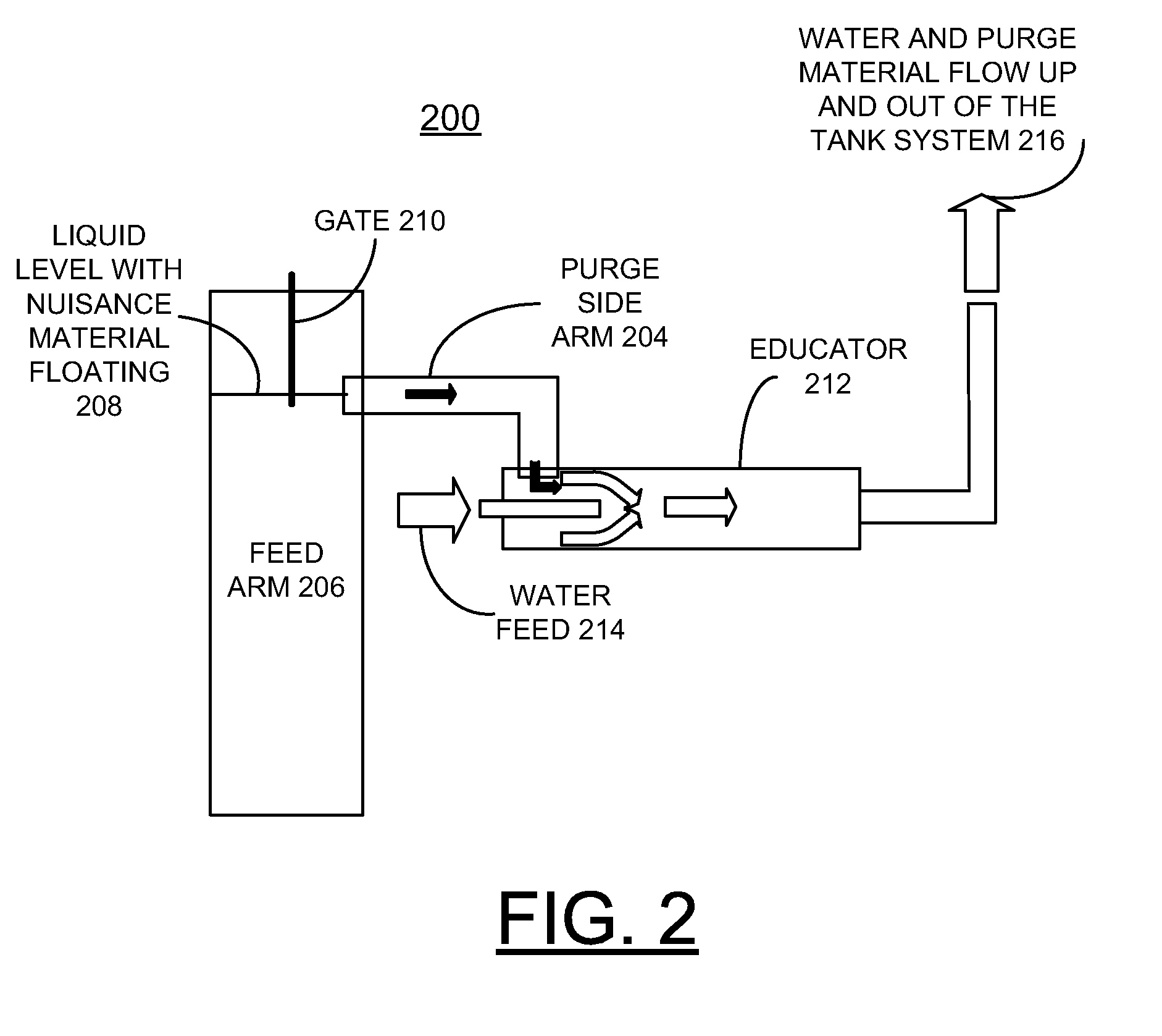
An elutriation column is installed in a separation tank. The elutriation column includes a vertical separation column having a first side feed arm and a second side overflow arm spaced above the first side feed arm. Water is forced upwardly through the vertical separation column at a controllable velocity. A solid feed mixture is fed through the first side feed arm to the vertical separation column. Water from the tank rising in the vertical separation column at the controlled velocity causes targeted floater materials to move upwardly in the vertical separation column and heavier sinker materials to continue to sink. The floater materials flow from an outlet in the side of the separation tank into the recovery tank. At a discharge, lower end of the vertical separation column, the heavier sinker materials are removed from the separation tank. A mechanism is provided for purging undesirable materials that can cause plugging from the feed arm.

Description

[0001]This application claims the benefit of U.S. Provisional Application No. 61 / 100,684 filed on Sep. 26, 2008.CONTRACTUAL ORIGIN OF THE INVENTION[0002]The United States Government has rights in this invention pursuant to Contract No. W-31-109-ENG-38 between the United States Government and The University of Chicago and / or pursuant to Contract No. DE-AC02-06CH11357 between the United States Government and UChicago Argonne, LLC representing Argonne National Laboratory.FIELD OF THE INVENTION[0003]The present invention relates to a process and apparatus for separating solid mixtures.DESCRIPTION OF THE RELATED ART[0004]The separation of solids mixtures, such as mixtures of plastics, metals or other solid chip-sized materials such as polymer mixtures derived from shredder residue is important so that valuable materials can be recovered and recycled, and residual materials can be recovered and disposed of in an environmentally safe manner.[0005]Recycling of different types of polymers ha...

Claims


Application Information

Patent Timeline
Patent Type & Authority Applications(United States)
IPC IPC(8): B03B5/66B03B11/00B03B5/62
CPCB03B5/623B03B2011/008B03B11/00
Inventor JODY, BASSAM J.SPANGENBERGER, JEFFREY S.POMYKALA, JR., JOSEPH A.DANIELS, EDWARDS J.LOCKWOOD, SCOTT T.
Owner UCHICAGO ARGONNE LLC
Learn More