Self Restrained Ductile Iron Fitting

Inactive Publication Date: 2010-04-01
S & B TECHN PRODS
View PDF8 Cites 29 Cited by
  • Summary
  • Abstract
  • Description
  • Claims
  • Application Information

AI Technical Summary

Benefits of technology

[0024]The sealing surface of the trailing portion of the-ring-shaped body extends further radially inward in a direction of a centerline of the mouth opening of the fitting than do the gripping teeth on the inner planar surfaces of the gripping segments. The C-shaped recess provided in the relatively rigid portion of the ring-shaped body includes a sloping wall portion which defines a ramp surface of the gripping ring as the mating male pipe is installed to form a pipe joint. The ring-shaped body can be provided in the form of a dual durometer gasket having a leading portion of a relatively higher durometer rubber and a trailing portion formed of a relatively lower durometer rubber. Alternatively, the leading portion of the ring-shaped body is formed of a hard plastic. The leading portion of the ring-shaped body could also be formed of a metal, a metal alloy, or other relatively rigid material in some cases, depending upon the exact nature of the male pi

Problems solved by technology

Wherever the pipeline changes direction or diameter, such as at a bend, tee or a reducer, however, the hydrostatic forces create an unbalanced thrust force in the line.
This unbalanced thrust force can cause the line to move or its joints to separate unless the thrust force is counterbalanced in some manner.
However, when higher pressures, poor soil conditions or significant changes of direction or diameter ar

Method used


Image

  • Self Restrained Ductile Iron Fitting
  • Self Restrained Ductile Iron Fitting
  • Self Restrained Ductile Iron Fitting

Examples


Embodiment Construction

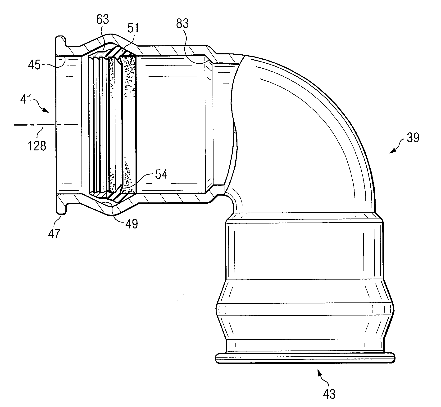
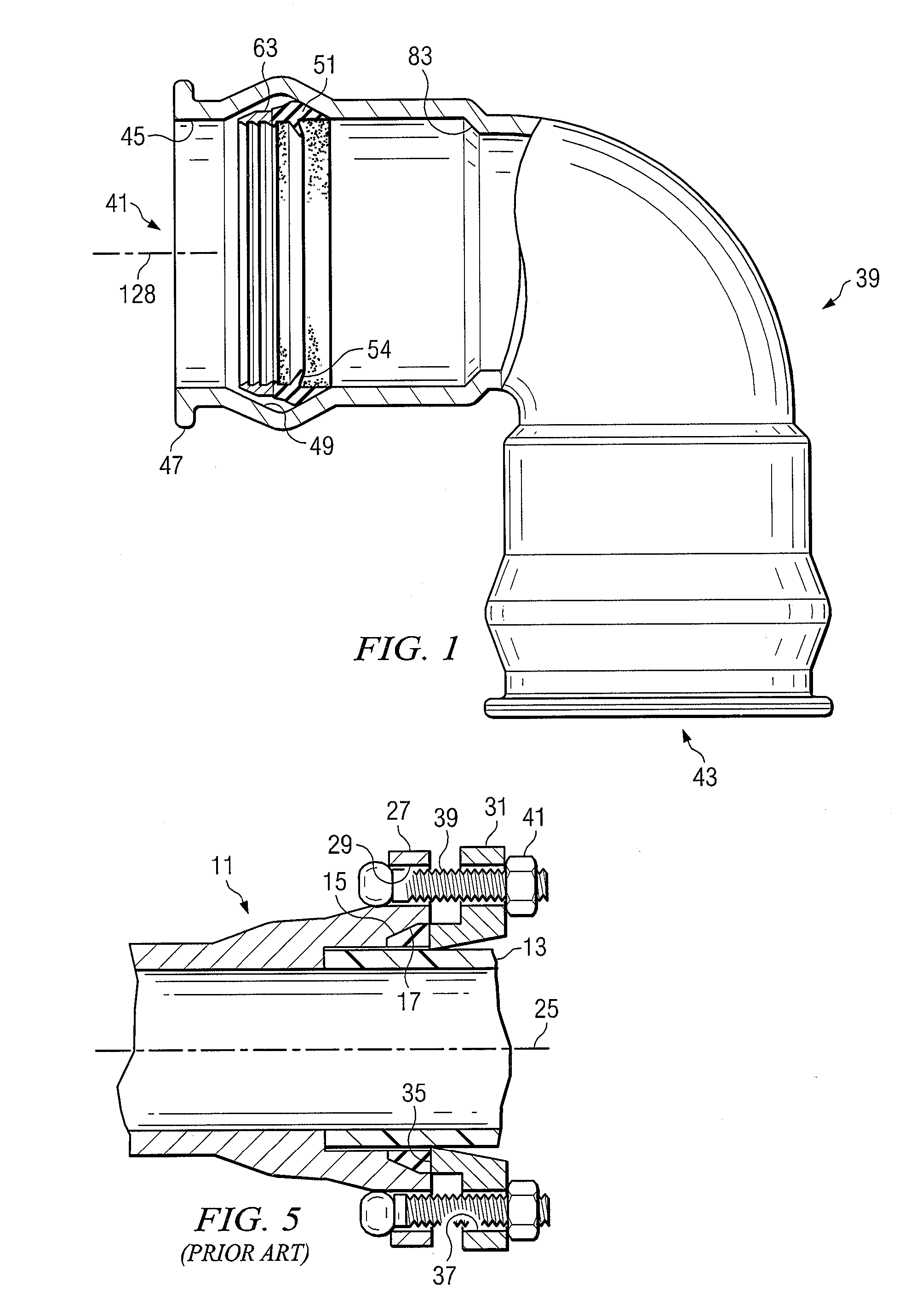
[0040]The present invention deals with piping systems of the type used in water, sewage and other municipal fluid conveyance systems. In the past, such pipelines were traditionally formed of a ferrous metal. By “ferrous metal” is meant iron and alloys of iron. For example, one type of ferrous metal which is commonly encountered in the water works industry is “ductile iron.” This particular type of metal is widely used because it offers a combination of a wide range of high strength, wear resistance, fatigue resistance, toughness and ductility in addition to the well-known advantages of cast iron-castability, machineability, damping properties and economy of production. It takes its name from the fact that it is “ductile” in nature, rather than being brittle, as was the case with earlier cast iron products and materials. Today, grades of ductile iron are available offering the option of choosing high ductility with grades guaranteeing more than 18% elongation, or high strength, with ...


PUM


Abstract

A combination sealing and restraint system for an as-cast ductile iron fitting is shown for both sealing and preventing separation of an iron pipe fitting and a mating male pipe. A ring-shaped body is installed within a mating groove provided in a mouth region of the as-cast fitting after the fitting has been cast at the manufacturing plant. The ring-shaped body is formed of an injection molded elastomeric material and carries a series of gripping segments which have teeth on an inner surface thereof which are designed to engage an outer surface of a mating male pipe. The teeth are oriented to allow movement of the male pipe in a first direction relative to an end opening o f the fitting during assembly, but to resist movement in a opposite direction after the fitting joint has been assembled. The gripping segments are mechanically bonded to the elastomeric body of the gasket during the injection molding operation. The ring-shaped body also includes a relatively flexible portion formed of an elastomer which forms a lip seal region with the mating male pipe.

Description

CROSS-REFERENCE TO RELATED APPLICATIONS[0001]The present application is a continuation-in-part of Applicant's prior U.S. application Ser. No. 12 / 199,954, filed Aug. 28, 2008, entitled “Self-Restrained Ductile Iron Fitting”, which was a continuation-in-part of Applicant's prior U.S. application Ser. No. 12 / 038,544, filed Feb. 27, 2008, entitled “Self-Restrained Ductile Iron Fitting,” which was, in turn, a continuation-in-part of Ser. No. 11 / 149,988, filed Jun. 10, 2005, entitled “Self Restrained Fitting for PVC and Ductile Iron Pipe.”BACKGROUND OF THE INVENTION[0002]1. Field of the Invention[0003]The present invention relates generally to the field of pipe connections for sections of pipe such as those pipes used in the municipal water and sewer pipeline industries. More particularly, this invention relates to a combination sealing and restraint system for use in “as-cast” ductile iron pipeline systems.[0004]2. Description of the Prior Art[0005]Pipes are commonly used for the conveya...

Claims


Application Information

Patent Timeline
IPC IPC(8): F16L17/025
CPCF16L21/03F16L37/0845F16L37/0925
Inventor JONES, JIMDARCE, GERARDOCHINCHILLA, RANDALLCORBETT., JR., BRADFORD G.CASTRO, MARCO
Owner S & B TECHN PRODS
Why Eureka
Try Eureka