Calibrating apparatus and method

a technology of image processing and light sensor, applied in the field of image processing, can solve the problems of erroneous judgment of the touch point input by the user, serious affect and worsen the state of the input touch point, so as to increase the accuracy of the state of the detected touch point or the state of gesture recognition

Active Publication Date: 2010-04-01
QUANTA COMPUTER INC
View PDF7 Cites 57 Cited by
  • Summary
  • Abstract
  • Description
  • Claims
  • Application Information

AI Technical Summary

Benefits of technology

[0009]A scope of the invention is to provide a calibrating apparatus and method which can be applied in an image processing apparatus. The position and the angle of a light sensor in the image processing apparatus can be...

Problems solved by technology

However, if the position or the angle of the light sensor in the optical touch screen is not installed well, the precision of the state of the detecte...

Method used


Image

  • Calibrating apparatus and method
  • Calibrating apparatus and method
  • Calibrating apparatus and method

Examples


first embodiment

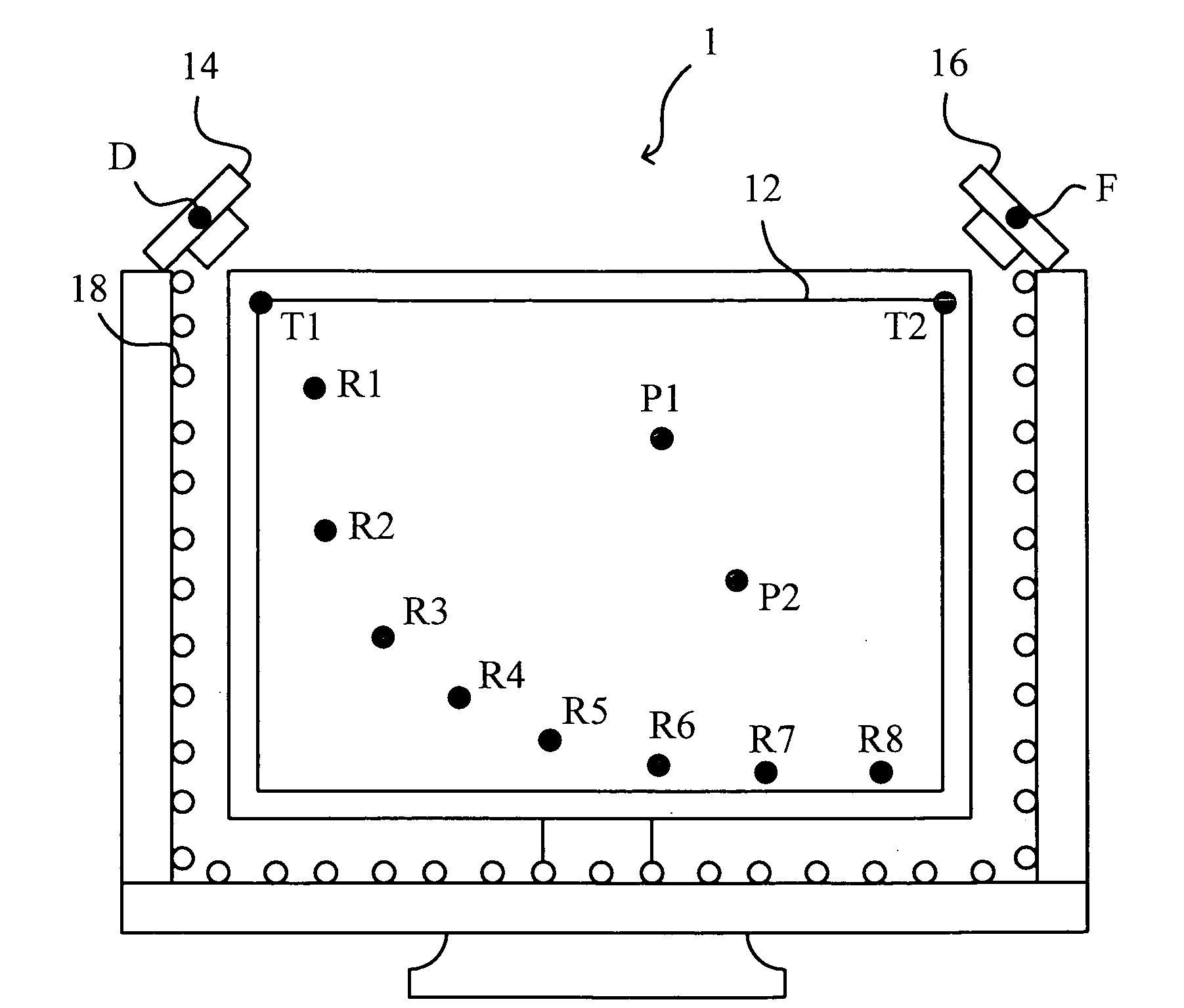
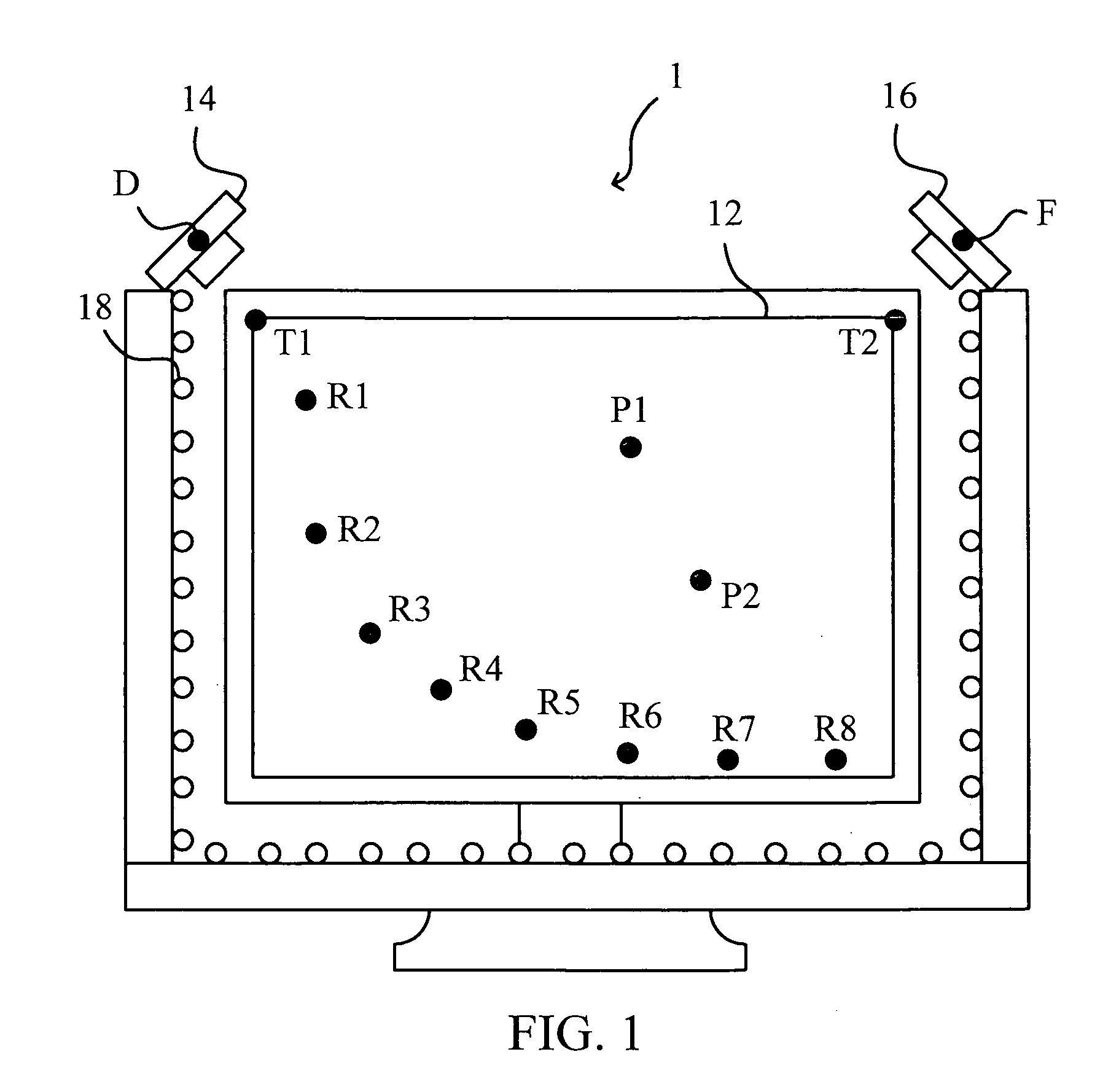
[0034]The first embodiment according to the invention is a calibrating apparatus. The calibrating apparatus is capable of calibrating the position and the angle of a light sensor in an image processing apparatus (such as an optical touch screen). Please refer to FIG. 1. FIG. 1 is a schematic diagram illustrating an optical touch screen. As shown in FIG. 1, the optical touch screen 1 includes a panel 12, a first light sensor 14, a second light sensor 16, and a plurality of light unit 18 (such as LEDs). The first indicating point P1, the second indicating point P2, and the eight reference points R1˜R8, whose coordinates are already known, are displayed on the panel 12. In one practical application, the first indicating point P1, the second indicating point P2, and the reference points R1˜R8 are used to be touched with users' fingers or other objects (such as a stylus) on the panel 12 for calibrating.

[0035]In the embodiment, the first light sensor 14 is disposed at the first predetermi...

second embodiment

[0058]The second embodiment according to the invention is a calibrating method. The calibrating method can be applied in an image processing apparatus (e.g., an optical touch screen) which includes a panel and at least one light sensor and can be performed to calibrate the position and the angle of the at least one light sensor. In the embodiment, a first indicating point, a second indicating point, and a plurality of reference points, whose coordinates are already known, are displayed on the panel. The at least light sensor is located at a predetermined position near a specific point on the circumference of the panel.

[0059]Please refer FIG. 7. FIG. 7 is a flow chart diagram illustrating the calibrating method according to the second embodiment of the invention. As shown in FIG. 7, the calibrating method can be substantially divided into two stages. In the first stage (step S10˜S11), the calibrating method will be performed to determine a predetermined position of the at least one l...


PUM


Abstract

A calibrating apparatus for an image processing apparatus is disclosed. The calibrating apparatus comprises a first operating module and a second operating module. The first operating module determines a third indicating point and a fourth indicating point according to a first indicating point, a second indicating point, and a specific point, and determines a calibration point (i.e. the predetermined position of a sensor) according to a first line through the first indicating point and third indicating point and a second line through the second indicating point and fourth indicating point. The second operating module forms reference lines according to reference points and the calibration point, forms reference angles according to the reference lines and a parallel line, generates reference coordinates of the reference points in an image and generates a calibration function according to the reference coordinates of the reference points and the reference angles.

Description

BACKGROUND OF THE INVENTION[0001]1. Field of the Invention[0002]The invention relates to image processing, and more particularly to a calibrating apparatus and method for calibrating a light sensor of an image processing apparatus.[0003]2. Description of the Related Art[0004]In recent years, with the advances in image processing technology, a variety of input methods (e.g., utilizing a touch panel, voice inputting, gesture inputting, etc.) which are convenient to users are gradually getting much more attention by the market and are flourishing.[0005]Generally, a common optical touch screen usually includes at least two light sensors for detecting the states of the touch points on the screen. For example, when the user emits light (such as through a light pen) on an optical touch screen to form a light point, the optical touch screen can capture the image corresponding to the screen with the light sensor and determine the coordinate of the light point on the screen with image process...

Claims


Application Information

Patent Timeline
IPC IPC(8): G06F3/042
CPCG06F3/0428G06F3/0418
Inventor CHIANG, CHING-CHUNHUANG, YI-MINGLIU, YUN-CHENGCHANG, CHIN-KANG
Owner QUANTA COMPUTER INC
Why Eureka
Try Eureka