[0006]In the present disclosure, the foregoing described problem of glare is addressed by providing a film for reducing reflections of ambient light on a display screen while maintaining efficient transmission of light emitted from the display screen. The film has a light receiving face and a light emitting face, and the film includes an arrayed plurality of truncated tapered structures projecting from the light receiving face to the light emitting face. Each of the plurality of truncated tapered structures has a relatively wider base positioned at the light receiving face, and a relatively narrowed top positioned at the light emitting face. The plurality of truncated tapered structures define a void region in the vicinity of the light emitting face between adjacent ones of the plurality of truncated tapered structures. The film further includes a dark material applied in the void region.
[0007]By virtue of the foregoing arrangement, it is ordinarily possible to guide the light emitting from the display screen using the plurality of truncated tapered structures so as to maintain a high percentage of
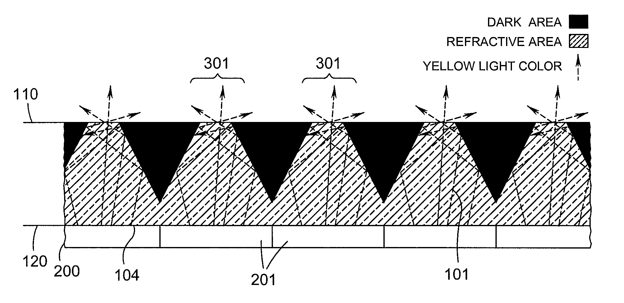
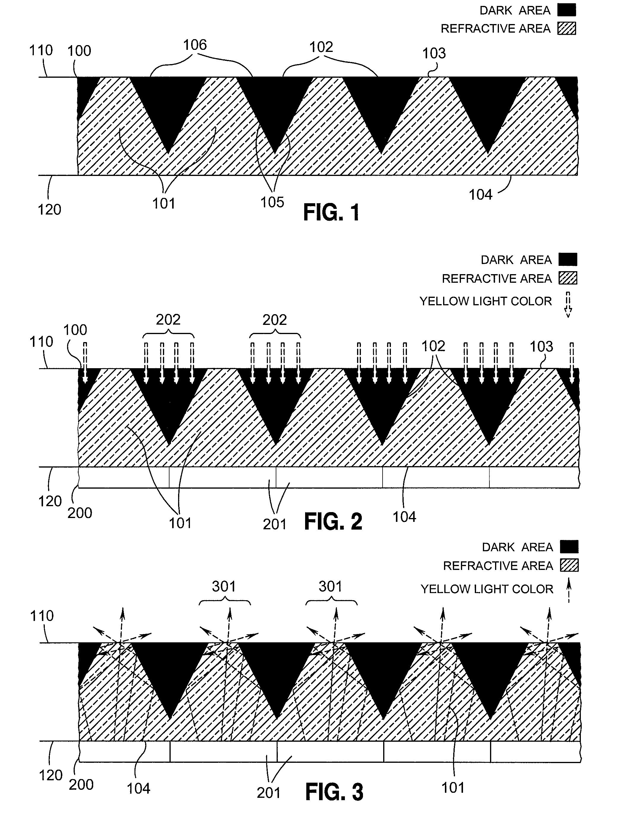
transmission rate of the emitting light. More precisely, light emitted from the display screen and received at the light receiving face of the film is not substantially blocked or absorbed by the film, but rather enters into the relatively wider bases of the truncated tapered structures. Through internal reflections inside the truncated tapered structures, substantially all such light is in turn emitted from the light emitting face without significant loss in brightness to thereby preserve the brightness of a picture to be viewed on the display screen. In addition, by virtue of the dark material applied in the void region, a substantial percentage of ambient light received at the light emitting face is absorbed so as to not reflect from the film or from the display screen beneath the film. Thus, a substantial amount of possible glare is reduced. In this regard, since the ambient light is absorbed, rather than scattered or reflected at a wider angle, or filtered using a polarization filter, glare produced by all light is substantially reduced. In this regard, the film substantially reduces glare when the glare is produced by light coming from all angles (i.e., anywhere from 0 degree to 90 degree polar angle, and from 0 degree to 180 degree
azimuth angle), when the glare is produced by all light having any polarization (i.e., any combination of s and p lights), and when the glare is produced by all light in the visible
wavelength. Moreover, by absorbing the ambient light using the dark material, the dark material prevents light from entering into the internal structures of the display screen. Thus, the dark material substantially prevents a secondary glare caused by ambient light entering the internal structure of the display screen and reflecting from structures and surfaces of the display screen. In general, the
transmission rate of the emitting light from the display screen is defined as the
signal, and the ambient light reflecting from the display screen is defined as
noise. Thus, the film provides the advantageous effect of substantially increasing the
signal-to-
noise ratio of the display screen.
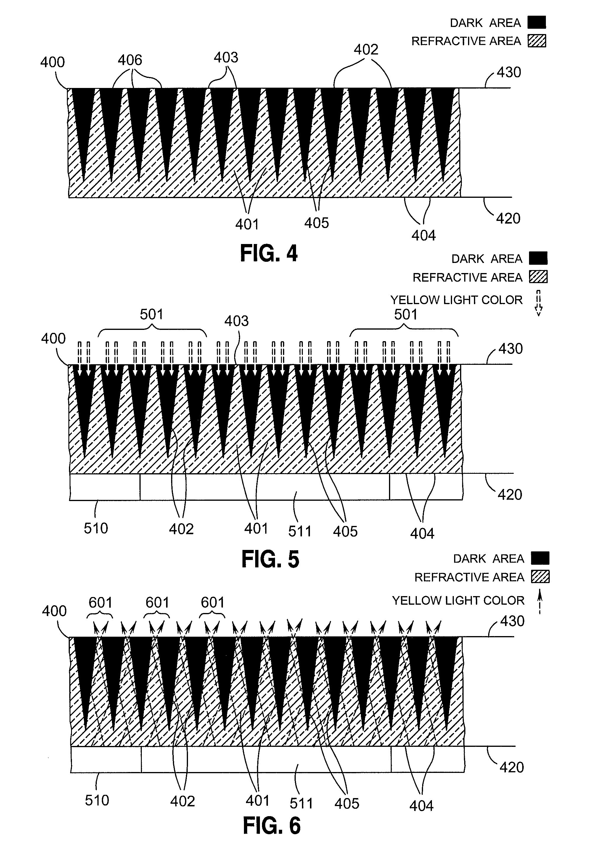
[0008]According to one aspect of the present disclosure, the display screen includes an array of light emitting pixels, wherein the base of each truncated tapered structure is sized in close correspondence to a size of a pixel of the display screen. In this aspect, each truncated tapered structure is positioned so as to be aligned with a corresponding one of the arrayed pixels of the display screen. In addition, the film has a sufficient thickness to support a ratio of an area of the base to an area of the top of each truncated tapered structure which is larger than 1:1. For example, if the film has a thickness of at least 670 microns, then the film can support a ratio of an area of the base to an area of the top of each truncated tapered structure in a range substantially around 1:1 to 10,000:1. The foregoing arrangement provides the advantageous effect of substantially increasing the
signal-to-
noise ratio of the display screen as described above, while maintaining a wide viewing angle for users of the display screen. In particular, a wide viewing angle is maintained because the size of the truncated tapered structures allows light emitting from the display screen to emit from the top of each truncated tapered structure at wider angles.

