Light source apparatus
a technology of light source and endoscope, which is applied in the field of light source apparatus, can solve the problems of low light guiding efficiency up to the irradiated light emitting portion at the front end of the endoscope, large size of light source apparatus such as the xenon lamp, and high cos
- Summary
- Abstract
- Description
- Claims
- Application Information
AI Technical Summary
Benefits of technology
Problems solved by technology
Method used
Image

Examples
first embodiment
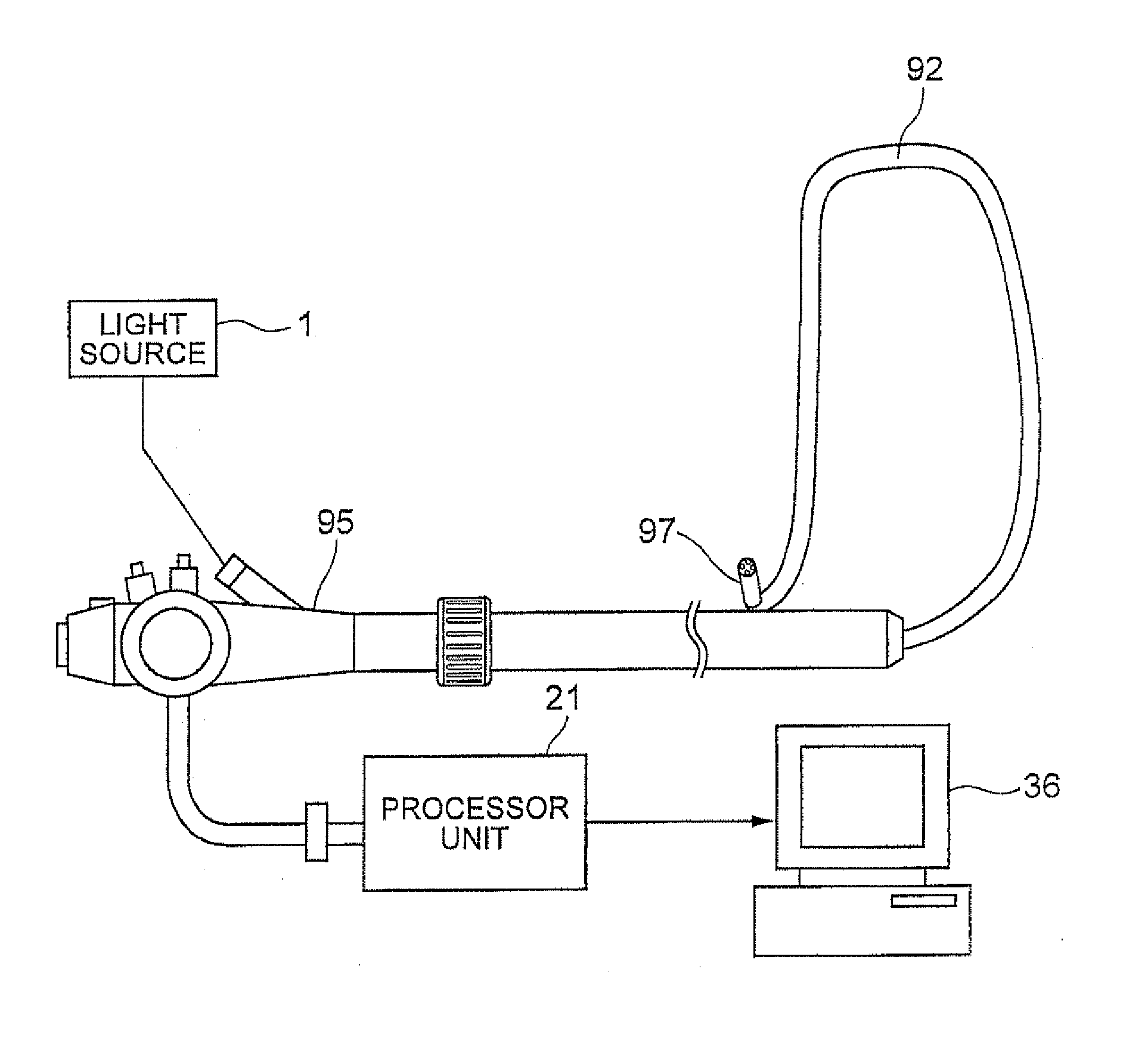
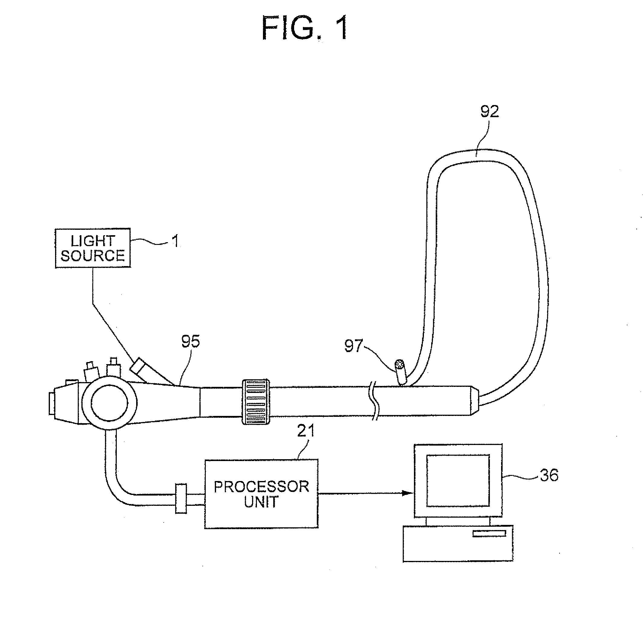
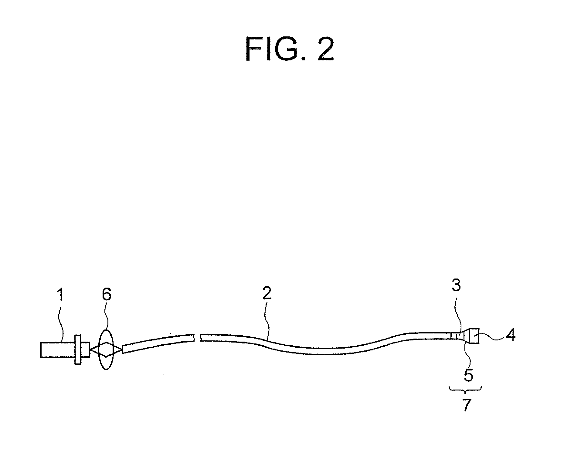
[0045]A semiconductor light source apparatus which can be used in an endoscope, according to a first embodiment of the present invention will be described below while referring to FIG. 1 and FIG. 2. FIG. 1 is a diagram showing an overall structure of the semiconductor light source apparatus which can be used in an endoscope, and FIG. 2 is a diagram showing a structure of main components of the semiconductor light source apparatus.
[0046]As shown in FIG. 1, the semiconductor light source apparatus of the first embodiment includes an endoscope insert portion 92, a endoscope front-end unit portion 97 which is connected to one end portion of the endoscope insert portion 92, an operating portion 95 which is connected to the other end portion of the endoscope insert portion 92, a light source 1 which supplies excitation light to a optical fiber which is disposed inside the operating portion 95 and the endoscope insert portion 92, a processor unit 21 which carries out signal processing of i...
modified embodiment of first embodiment
[0085]A semiconductor light source apparatus of a modified embodiment of the first embodiment of the present invention will be described below while referring to FIG. 6 and FIG. 7. FIG. 6 is a diagram showing a cross-sectional structure (view) of the front-end unit portion 7, and FIG. 7 is a diagram in which, a beam spot of the excitation light at each of the concave lens 3, a convex lens 15, and the wavelength converting member 4 is shown. Firstly, a structure of the modified embodiment of the first embodiment will be described below.
[0086]In FIG. 6 and FIG. 7, members denoted by the same reference numerals as the members denoted in FIG. 3 which is a structural diagram of the first embodiment are similar members, and detail description thereof is omitted. At the interior of the holding member 8, in other words, inside the cavity 30, the optical fiber 2, the concave lens 3, the convex lens 15; the wavelength converting member 4, the concave lens fixing portion 11, a convex lens fixi...
second embodiment
[0101]A semiconductor light source apparatus according to a second embodiment of the present invention will be described below while referring to FIG. 8. FIG. 8 is a diagram showing a cross-sectional view of the front-end unit portion 7 of the semiconductor light source apparatus according to the second embodiment. The second embodiment differs from the first embodiment at a point that, a holding member 19 of the front-end unit portion 7 provided at a side of the emitting end portion Po of the optical fiber 2 is structured in which a taper inclination angle of the holding member 19 differs partially as shown in FIG. 8.
[0102]In FIG. 8, members denoted by same reference numerals as the members shown in FIG. 3 of the first embodiment are similar, and detail description thereof is omitted.
[0103]At interior of the holding member 19, in other words, inside the cavity 30, the optical fiber 2, the concave lens 3, the wavelength converting member 4, the concave lens fixing portion 11, the wa...
PUM
| Property | Measurement | Unit |
|---|---|---|
| distance | aaaaa | aaaaa |
| excitation wavelength | aaaaa | aaaaa |
| cladding diameter | aaaaa | aaaaa |
Abstract
Description
Claims
Application Information
 - R&D
- Intellectual Property
- Life Sciences
- Materials
- Tech Scout
- Unparalleled Data Quality
- Higher Quality Content
- 60% Fewer Hallucinations
Browse by: Latest US Patents, China's latest patents, Technical Efficacy Thesaurus, Application Domain, Technology Topic, Popular Technical Reports.
© 2025 PatSnap. All rights reserved.Legal|Privacy policy|Modern Slavery Act Transparency Statement|Sitemap|About US| Contact US: help@patsnap.com