
System And Method For Interference Mitigation In Wireless Networks

a wireless network and interference mitigation technology, applied in climate sustainability, sustainable buildings, high-level techniques, etc., can solve problems such as significant increase in problems, increased conflict, and inability to meet the needs of wireless networks, so as to increase throughput and maximize throughput

Active Publication Date: 2010-04-01
WISCONSIN ALUMNI RES FOUND
View PDF9 Cites 8 Cited by
  • Summary
  • Abstract
  • Description
  • Claims
  • Application Information

AI Technical Summary

Benefits of technology

The present patent is about a system and method for scheduling data packets in a wireless local area network. It uses a centralized scheduling system to handle most data packets, while also using speculative scheduling based on network characteristics to increase throughput. The system can also maximize throughput by transmitting groups of packets within defined time periods. The main technical effects of this patent are improved efficiency in transmitting data packets and better utilization of network resources.

Problems solved by technology

However, given the dynamic nature of wireless networks, such as users moving around using mobile computing devices, users dropping in to and out of the network, etc., conflicts increasingly occur.
When an access point attempts to transmit on a data channel, the channel may already be in use by another access point, creating the conflict.
However, DCF does not perform optimally for network that have hidden and / or exposed terminals.
Accordingly, the first wireless access point may begin transmitting, but such transmissions are not detectable by the other wireless access points such that any of the other wireless access points may simultaneously attempt to transmit causing overlapping transmissions.
The problem increases significantly when networks include a large numbers of wireless access points and associated computing devices, when networks are heavily utilized, etc. as often occurs with increasing usage of mobile computing devices, etc.

Method used


Image

  • System And Method For Interference Mitigation In Wireless Networks
  • System And Method For Interference Mitigation In Wireless Networks
  • System And Method For Interference Mitigation In Wireless Networks

Examples


Embodiment Construction

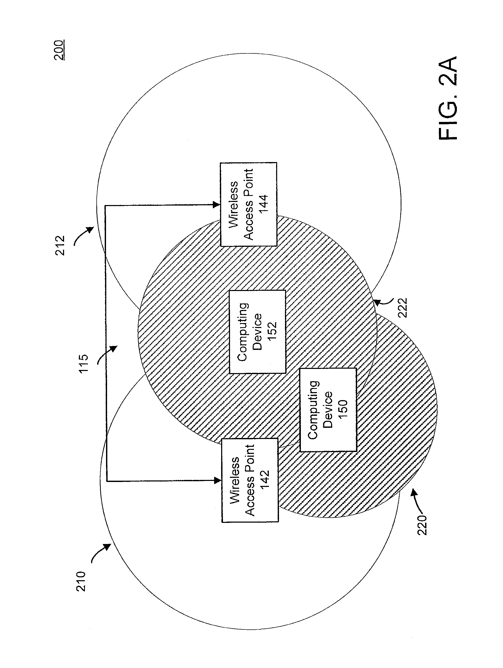
[0016]The present invention broadly discloses a centralized scheduling controller configured to identify exposed and hidden terminals. In one embodiment, the invention uses a conflict graph to schedule packets for transmission based on the conflict graph and a centralized scheduling algorithm. Advantageously, the conflict graph allows the centralized scheduling controller to use DCF scheduling for data transmission not involving detected hidden and / or exposed terminals and centralized scheduling for data transmissions involving hidden and / or exposed terminals, increasing the data throughput on the wireless network.

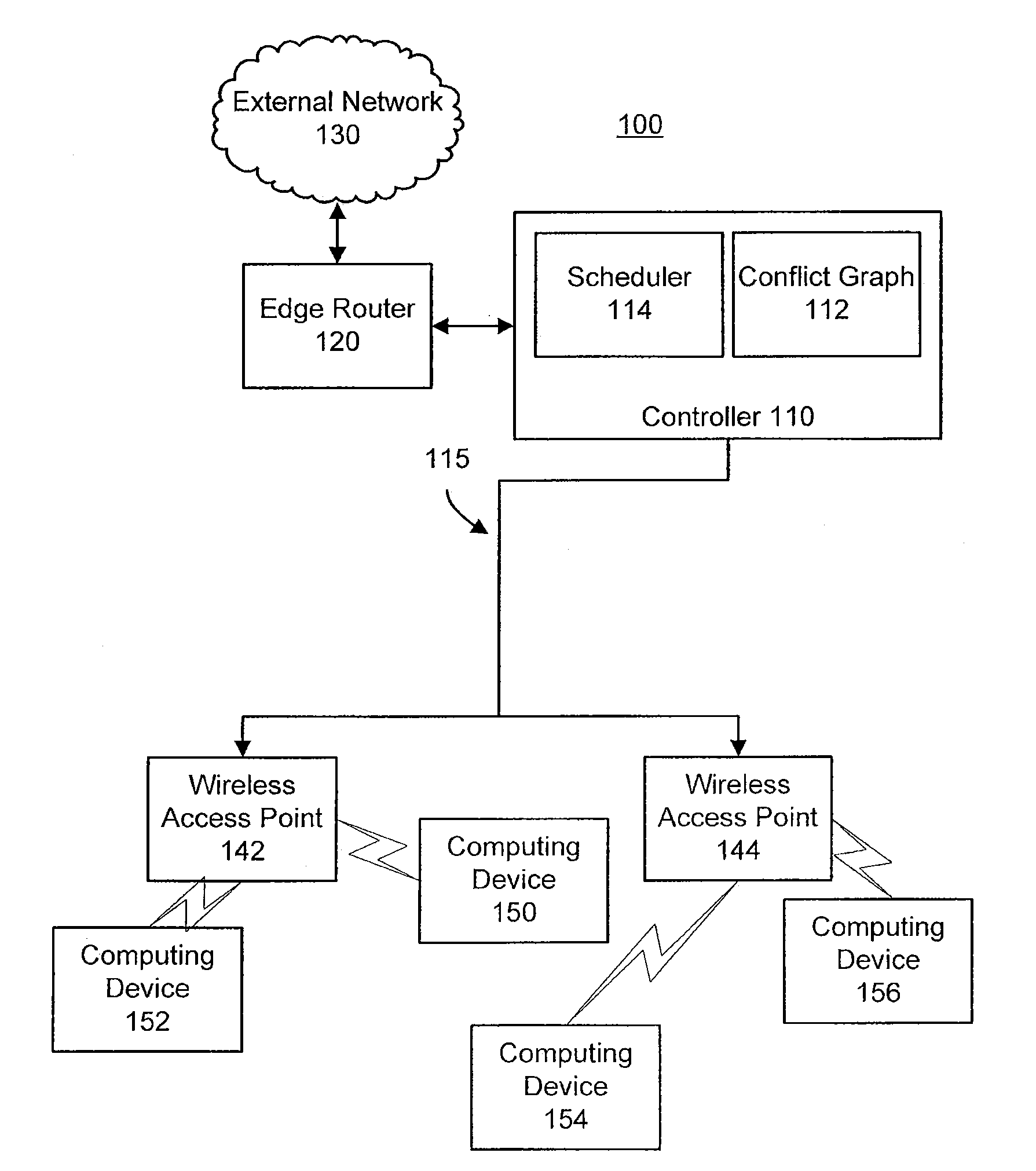
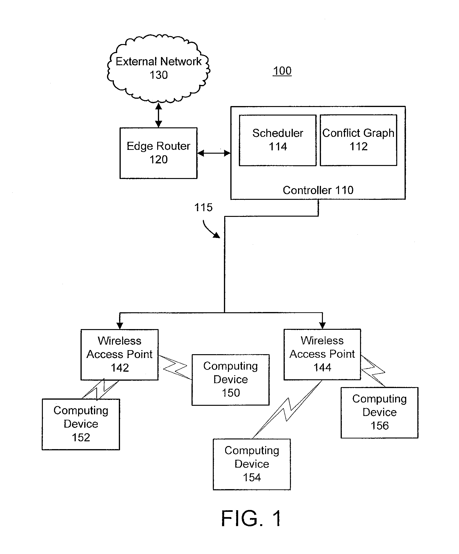
[0017]Referring now to FIG. 1, a graphical representation of a wireless local area network 100 having exposed and hidden terminals and including a centralized scheduling controller 110 is shown, according to an exemplary embodiment. Network 100 includes a centralized scheduling controller 110 connected to an external network 130 through an edge router 120. Controller 110 i...


PUM


Abstract

A computer-implemented method for scheduling a packet for transmission in a wireless local area network can be used to account for hidden and / or exposed terminals. The method includes determining whether the packet is to be transmitted to a computing device through a wireless access point that is in conflict with at least one other computing device associated with a different access point. The method further includes determining whether there is a conflicting packet scheduled to be transmitted for any conflicting computing devices associated with a different access points and scheduling the packet for transmission based on any conflicting packets. The method yet further includes forwarding the packet to a wireless access point at the scheduled time.

Description

CROSS-REFERENCE TO RELATED APPLICATIONS[0001]This application claims the benefit of U.S. Provisional Application No. 61 / 095,216 filed Sep. 8, 2008 and U.S. Provisional Application No. 61 / 097,406, filed Sep. 16, 2008, hereby incorporated by reference in its entirety.BACKGROUND[0002]Wireless local area networks (WLAN) are increasingly utilized by organizations to provide connectivity to users. As usage increases, the number of users, the number of wireless access points, the amount of traffic, etc. all increase to the point where maximizing throughput, the amount of data that can be delivered during any given time, becomes increasingly important. However, given the dynamic nature of wireless networks, such as users moving around using mobile computing devices, users dropping in to and out of the network, etc., conflicts increasingly occur. When an access point attempts to transmit on a data channel, the channel may already be in use by another access point, creating the conflict. Gene...

Claims


Application Information

Patent Timeline
Patent Type & Authority Applications(United States)
IPC IPC(8): H04W72/12H04L47/20
CPCH04L43/028H04L43/04H04L43/0835H04L45/742Y02B60/50Y02B60/46H04L69/22H04L69/12H04L47/20Y02D30/00
Inventor MISHRA, ARUNESHBANERJEE, SUMANSHRIVASTAVA, VIVEKRAYANCHU, SHRAVAN
Owner WISCONSIN ALUMNI RES FOUND
Learn More