Drive unit manufacturing method and drive unit

a technology of drive unit and manufacturing method, which is applied in the direction of transducer casing/cabinet/support, loudspeaker, electrical transducer, etc., can solve the problems of high labor intensity of workers, difficult integration of voice coils on printed boards by printing, and high optimal conditions of soldering for workers with little experience, so as to reduce the burden on manufacturing workers and improve product quality

Inactive Publication Date: 2010-04-01
SONY CORP
View PDF5 Cites 0 Cited by
  • Summary
  • Abstract
  • Description
  • Claims
  • Application Information

AI Technical Summary

Benefits of technology

[0018]As described up to this point, according to the present invention, it is possible to reduce the burdens on manufacturing workers and improve the product quality more than usual.

Problems solved by technology

This voice coil is hard to be integrally formed on the printed board by printing.
This makes the optimal conditions of soldering very severe for workers who have little experience.
Thus, manual soldering imposes large burden on the workers and much efforts are required for making the workers skilled in order to enhance the reliability.
Besides, it is also required to consider any human errors and it is difficult to maintain the constant quality.

Method used


Image

  • Drive unit manufacturing method and drive unit
  • Drive unit manufacturing method and drive unit
  • Drive unit manufacturing method and drive unit

Examples


first embodiment

[0044][1. Drive Unit of Headphone][0045][2. Drive Unit Manufacturing Apparatus][0046][3. Drive Unit Manufacturing Method][0047][4. Example of Effects of First Embodiment]

[1. Drive Unit of Headphone]

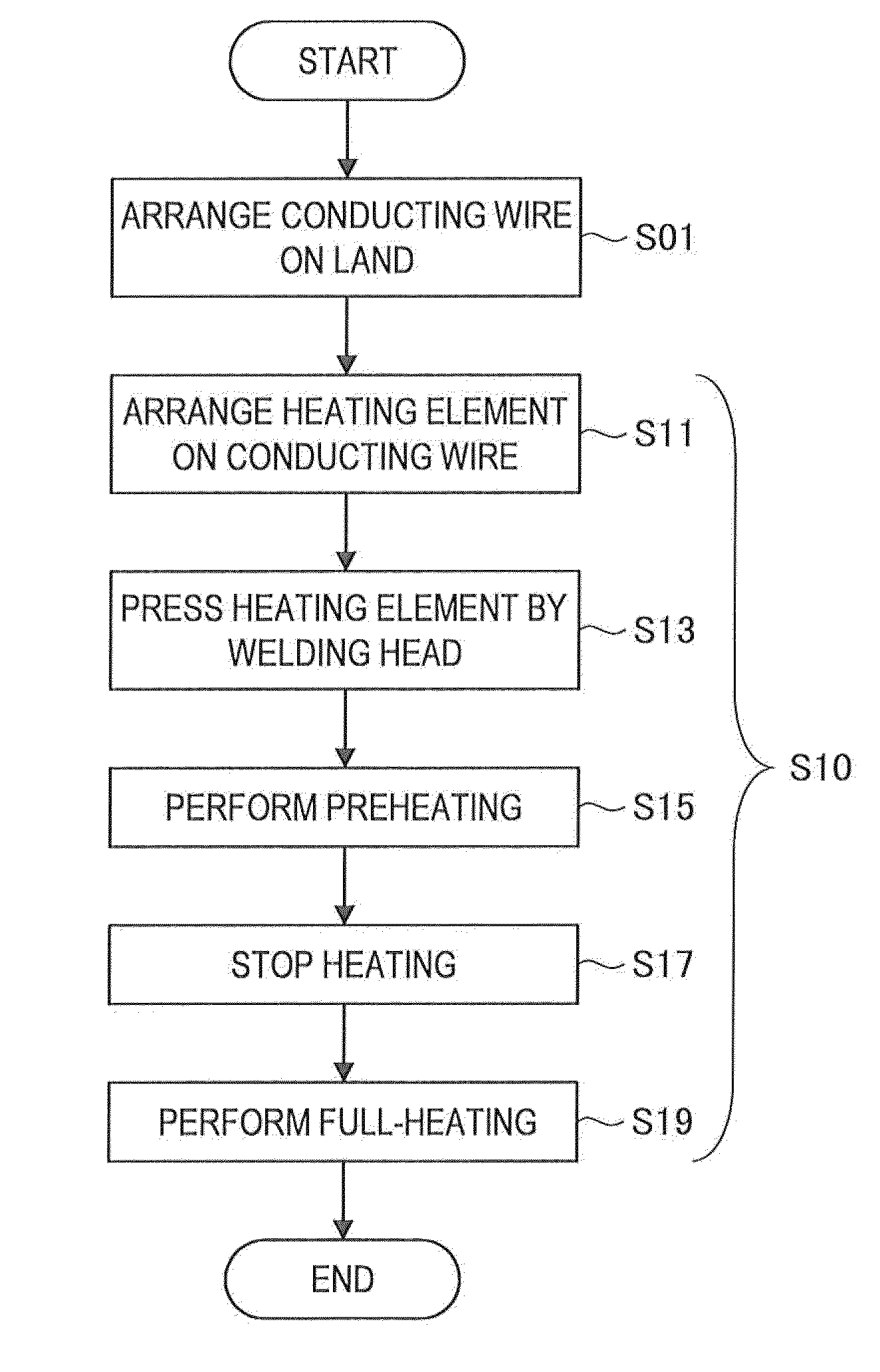
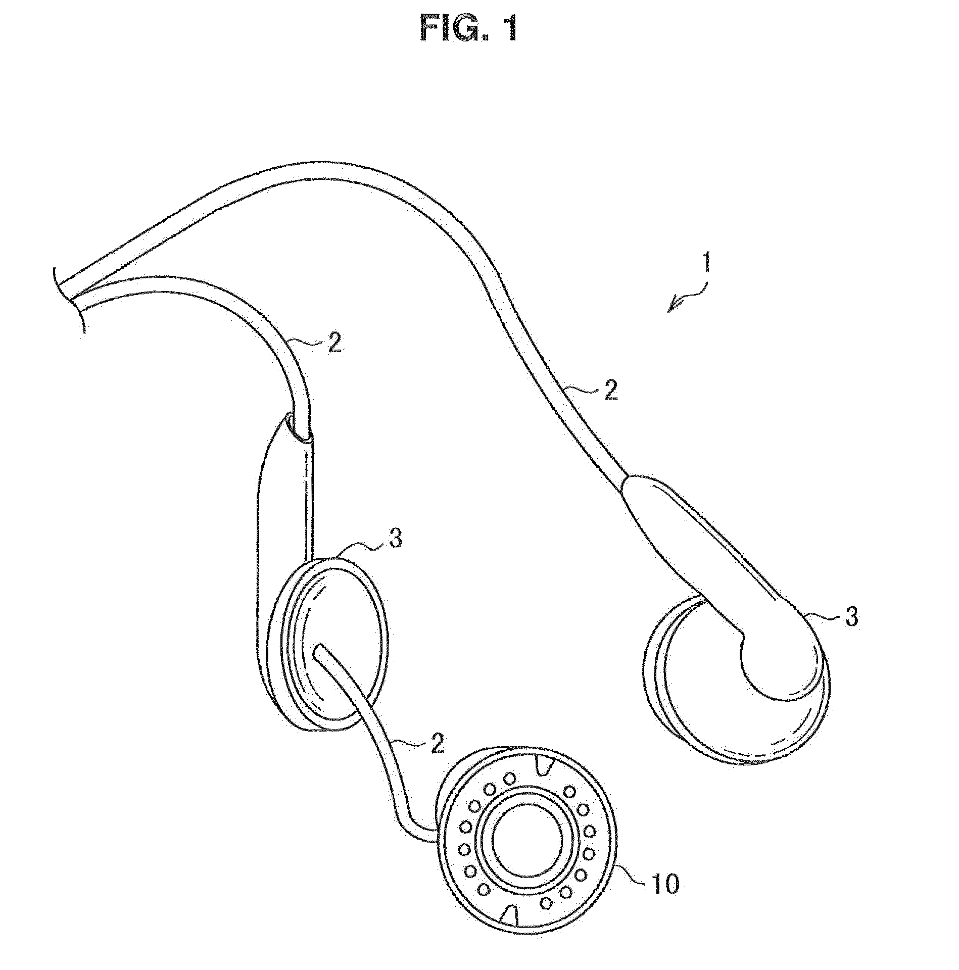
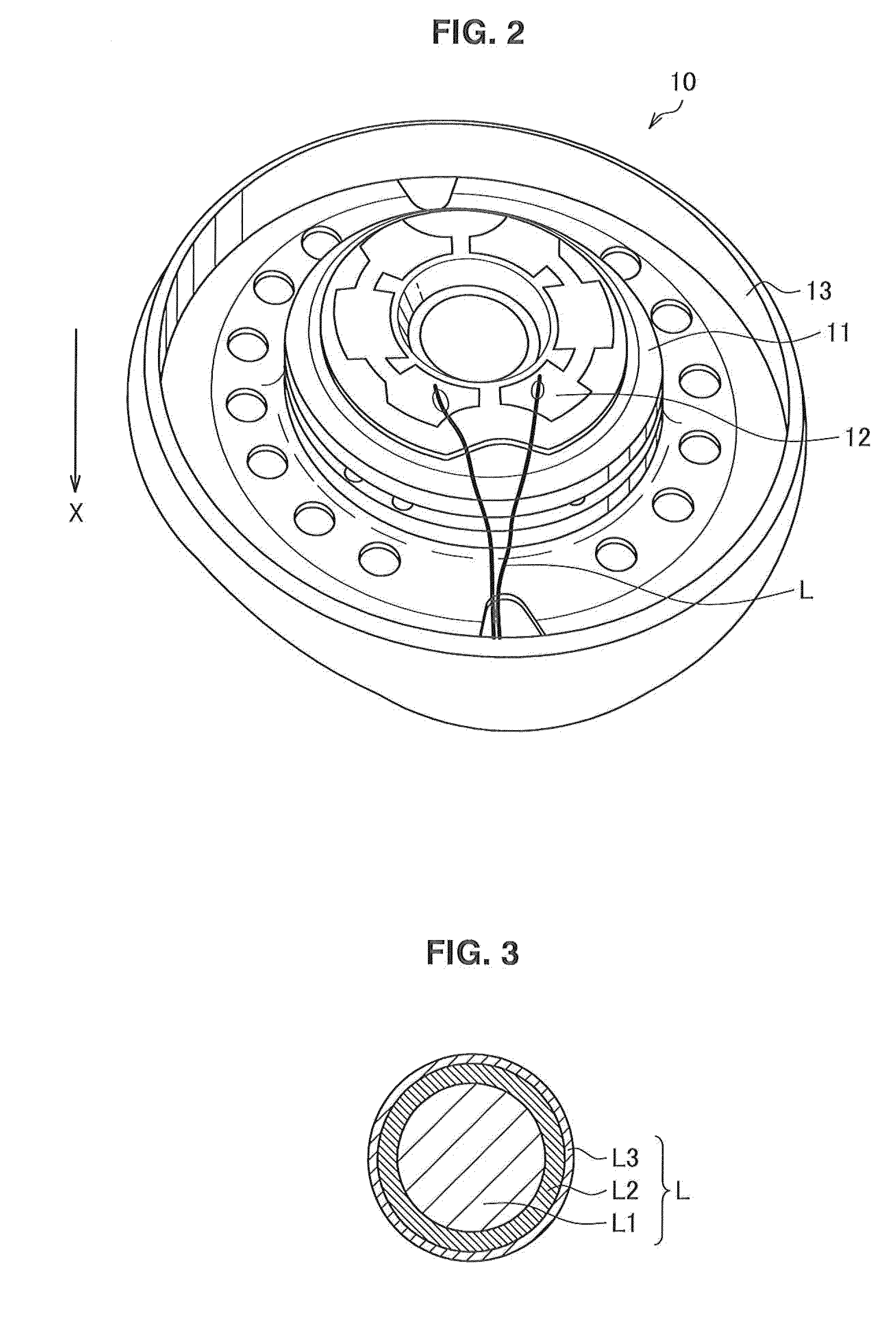
[0048]First description is made, with reference to FIGS. 1 to 4, about a drive unit according to a first embodiment of the present invention. FIG. 1 is an explanatory view for explaining the outline structure of a headphone according to a first embodiment of the present invention. FIG. 2 is an explanatory view for explaining a drive unit according to the present embodiment. FIG. 3 is an explanatory view for explaining a conducting wire according to the present embodiment, and FIG. 4 is an explanatory view for explaining welding between the conducting wire and a land in the drive unit according to the present embodiment.

[0049]FIG. 1 shows the structure of the inner ear type headphone 1. Such an inner ear type headphone 1 is miniaturized as it is mounted on a user's ear or inserted in into ...


PUM

PropertyMeasurementUnit
pressing forceaaaaaaaaaa
timeaaaaaaaaaa

Abstract

The present invention provides a drive unit manufacturing method including the steps of: preparing a conducting wire which contains at least copper and forms a voice coil for conversion between sound and electric signals and arranging the conducting wire on a land which is formed on a board that the voice coil is arranged on and is provided for transmitting the electric signals; and connecting the conducting wire and the land by resistance welding.

Description

BACKGROUND OF THE INVENTION[0001]1. Field of the Invention[0002]The present invention relates to a drive unit manufacturing method and a drive unit.[0003]2. Description of the Related Art[0004]In recent years, there are growing demands for enjoying sound like music in various scenes and to meet these demands, various sound reproducing apparatuses have been developed. Users can bring such a sound reproducing apparatus with them and listen to sound wherever and whenever they want. As more often users bring such sound reproducing apparatuses with them, portability of such sound reproducing apparatuses becomes more important. In order to enhance portability, various apparatuses are getting more and more miniaturized.SUMMARY OF THE INVENTION[0005]Such miniaturization of apparatuses depends on progress of the technique which allows finer-line circuits to be formed on a printed board or the like. However, a drive unit, which is equivalent to a sound output part such as a speaker or microph...

Claims


Application Information

Patent Timeline
Patent Type & Authority Applications(United States)
IPC IPC(8): H04R3/00H04R31/00
CPCH01F7/066H04R1/06Y10T29/49005H04R31/006H04R2201/105H04R1/1016
Inventor TAMAYAMA, RYUZOARAI, SATOSHIYAJIMA, MASARUSAKATA, KOJI
Owner SONY CORP
Why Eureka
Try Eureka