Undersea pipe-laying

a technology for pipelines and undersea pipes, which is applied in the direction of pipe laying vessels, cable laying vessels, pipe laying and repair, etc. it can solve the problems of difficult to provide welding stations on the tower, large support length, and unsatisfactory solutions, and achieve good protection of pipelines and enhance the accessibility of pipelines.

Active Publication Date: 2010-04-01
SAIPEM SPA
View PDF24 Cites 12 Cited by
  • Summary
  • Abstract
  • Description
  • Claims
  • Application Information

AI Technical Summary

Benefits of technology

[0014]Preferably the vessel hull includes, on the waterline and in the region of its first end, separate portions on opposite sides of the pipelaying path. By providing portions of the hull on each side of the pipeline as it passes into the water and through the surface region of the water, especially good protection to the pipeline is provided.
[0015]The separate portions may define an enclosed moonpool but preferably they define between them

Problems solved by technology

That is, however, an unsatisfactory solution because of the size and cost of the equipment required.
A problem with that solution is that the same tower has to be able to be operated over a wide range of angles, which, for example, makes it difficult to provide welding stations on the tower.
That, however, requires a considerable length of support, because the radius of bending to which the pipeline can be subjected is limited, especially in the case of large diameter pipelines.
The extra breadth of such a vessel and its relatively large draught are, however, disadvantag

Method used


Image

  • Undersea pipe-laying
  • Undersea pipe-laying
  • Undersea pipe-laying

Examples


Embodiment Construction

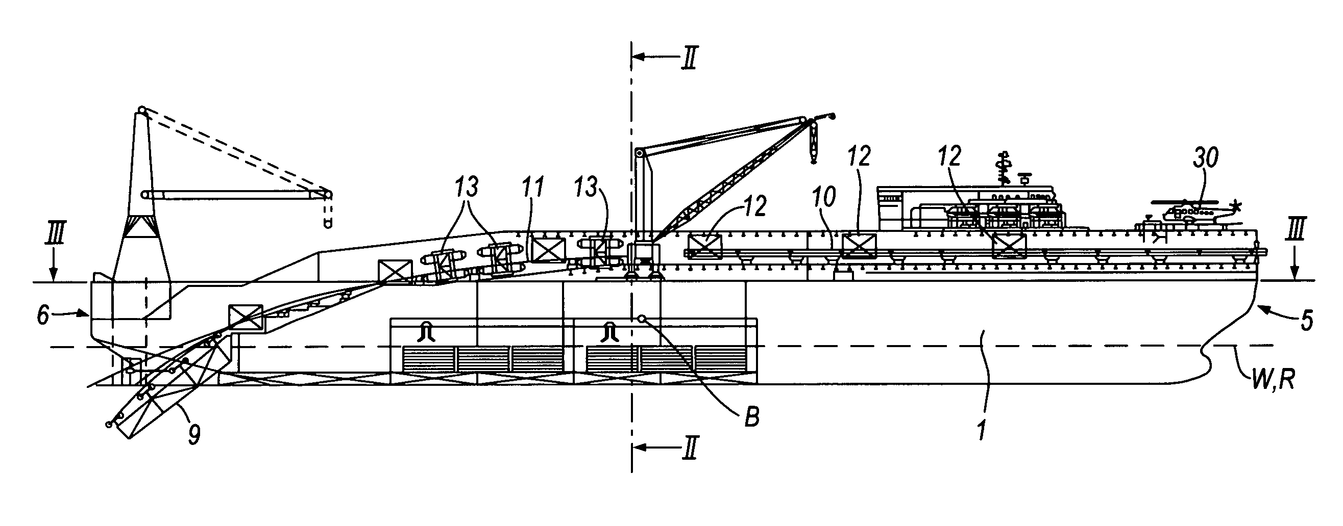
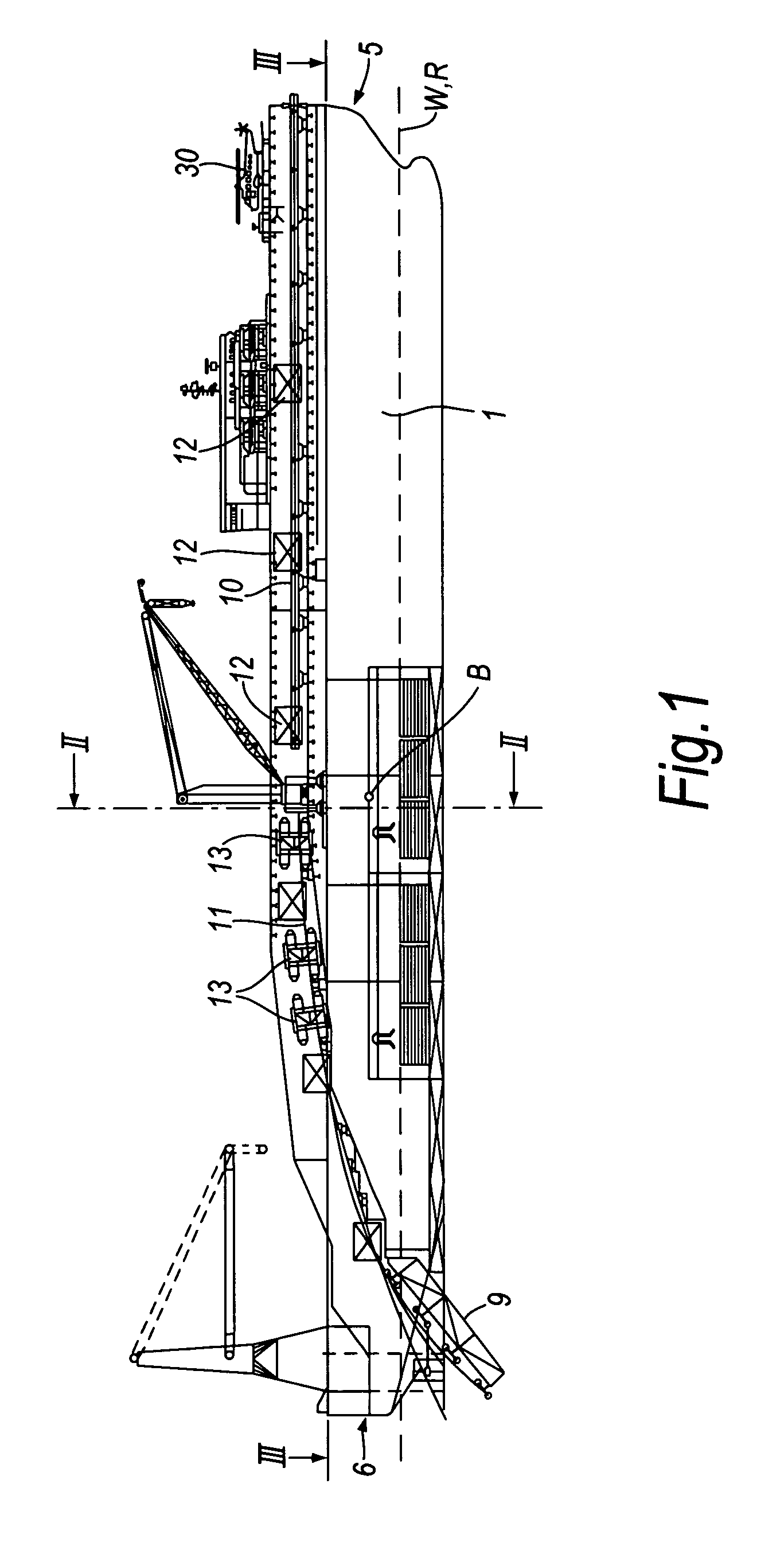
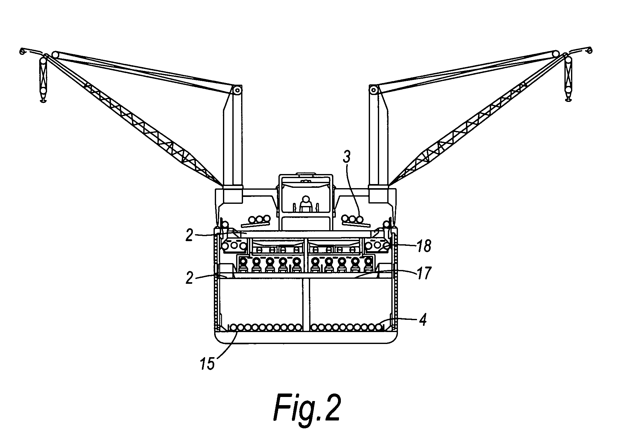
[0040]The vessel shown in FIGS. 1 to 3 generally comprises a vessel hull 1, within which are defined a plurality of prefabricated decks 2 for the prefabrication of jointed pipe sections 3 from individual lengths of pipe 4 and on which cranes and other facilities are provided. The bow 5 of the hull 1 is shown on the right hand side and the stern 6 of the hull 1 is shown on the left hand side, as viewed in FIG. 1.

[0041]As can be seen from FIGS. 1 and 3, the vessel hull 1 is of unconventional design at its stern end, having starboard and port end portions 7S and 7P between which an elongate recess 8 is defined. The recess 8 is open at the stern end of the hull 1 and is also open downwardly (into the sea), but it may be closed over the top by a deck. As shown in FIG. 1, but omitted in FIG. 3, an internal ramp 9 is pivotally connected to the hull of the vessel and is disposed in the protected stern area defined by the recess 8.

[0042]The barycentre B (centre of gravity) of the vessel is m...


PUM


Abstract

A monohull vessel for laying a pipeline includes tensioners 13 disposed along a Pipelaying path P. The pipelaying path P includes an upstream portion that is substantially horizontal and at least 10 m above the centre of rolling R of the vessel and, towards a stern end of the vessel hull, a downstream portion that is downwardly inclined and, in use, enters the water at a location inboard of the stern end of the vessel hull 1.

Description

TECHNICAL FIELD[0001]This invention relates to a vessel for laying a pipeline at sea and to a method of laying a pipeline. The invention is concerned particularly with the path along which the pipeline is guided by the vessel.BACKGROUND OF THE INVENTION[0002]When laying a pipeline at sea one of two methods is commonly used: either the “S” laying method or the “J” laying method. The two methods are named in accordance with the general shape adopted by the pipeline during laying. In “S” laying, the pipeline leaves the vessel at little or no inclination to the horizontal, adopts a steeper inclination in the water and then returns to a generally horizontal disposition on the seabed. In “J” laying, the pipeline leaves the vessel at a steep or vertical inclination and the inclination steadily reduces until the pipeline is in a generally horizontal disposition on the seabed. As interest in laying pipeline in deep water has increased, so “J” laying has become more attractive because the pip...

Claims


Application Information

Patent Timeline
IPC IPC(8): F16L1/12
CPCB63B35/03F16L1/20B63B35/04
Inventor BIANCHI
Owner SAIPEM SPA
Why Eureka
Try Eureka