Luno Geo Wind Mill

Inactive Publication Date: 2010-04-08
PINDRIK MICHAEL
View PDF5 Cites 5 Cited by
  • Summary
  • Abstract
  • Description
  • Claims
  • Application Information

AI Technical Summary

Problems solved by technology

Many conventional renewable recourse energy generation technologies, however, have design limitations, fragility, low benefit-to-cost ratio or inadequate expansion capacity.

Method used


Image

  • Luno Geo Wind Mill
  • Luno Geo Wind Mill
  • Luno Geo Wind Mill

Examples


Embodiment Construction

Of THE INVENTION

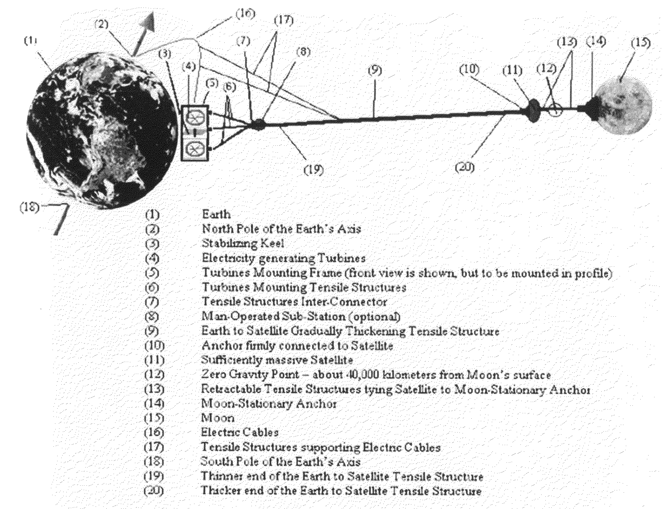
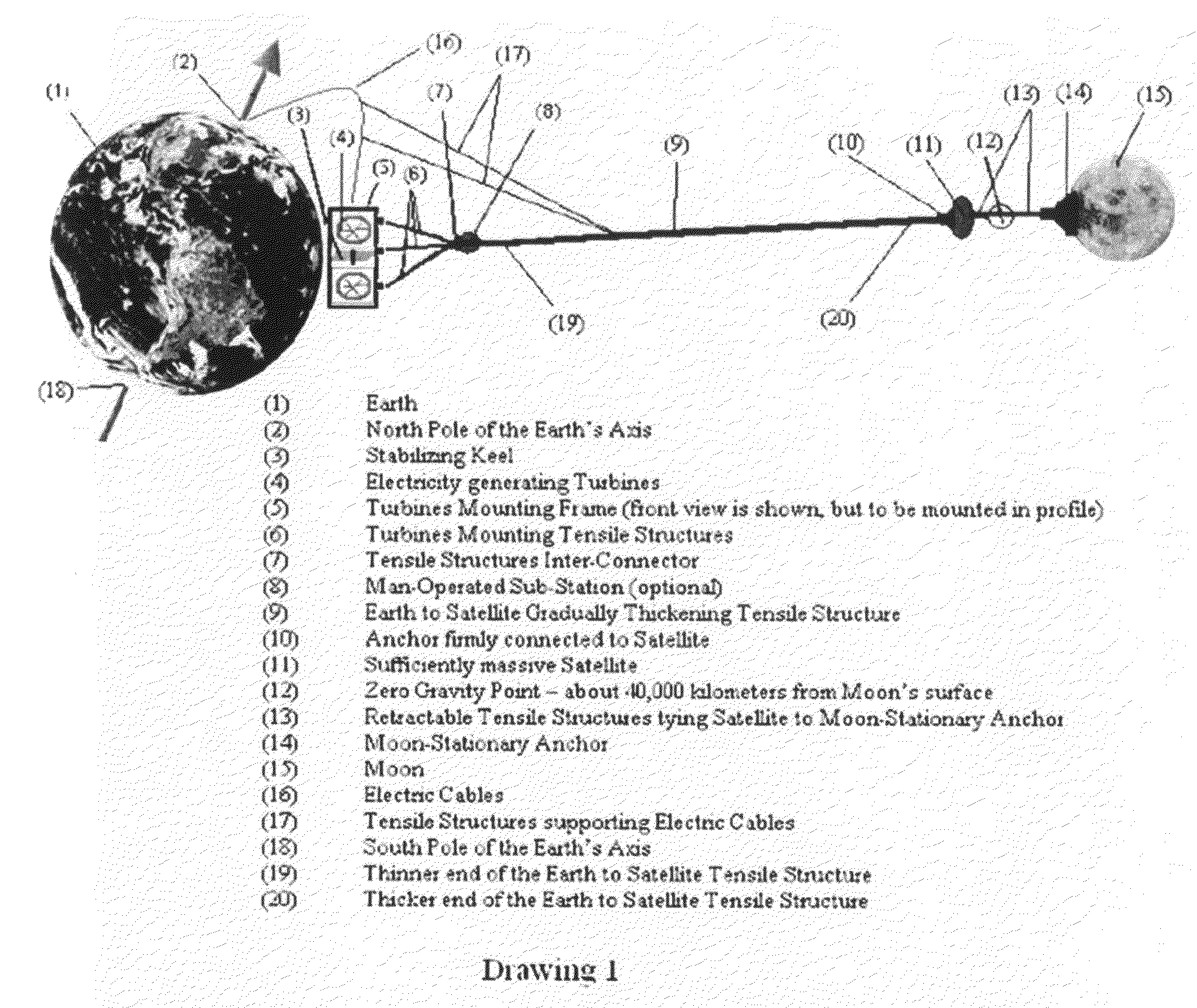
[0035]As stated in the BACKGROUND section, the Moon faces the Earth always with the same side. This allows a Moon-Stationary Anchor (14) to be firmly grounded on the side of the Moon facing the Earth. The tensile structure system (13) and (9) connected to this Moon-Stationary Anchor, being pulled by the Earth's gravitational force, will always point to the Earth.

[0036]The distance of the Zero Gravity Region from the Moon may be calculate from the formula:

Earth-Mass*Earth-Distance2=Moon-Mass*Moon-Distance2

[0037]From this formula we can obtain:

Earth-Distance2 / Moon-Distance2=Moon-Mass / Earth-Mass

[0038]Since Moon-Mass / Earth-Mass=1 / 81 (NASA Solar System Exploration), we have:

Earth-Distance2 / Moon-Distance2=1 / 81

[0039]From this we can obtain:

Earth-Distance / Moon-Distance=1 / 9

[0040]The distance of the Zero Gravity Region from the Moon=1 / (1+9)*385,000=38,500 [km]

[0041]The distance of the Zero Gravity Region from the Earth=385,000−38,500=346,500 [km].

[0042]As stated in the BACKGR...


PUM


Abstract

Super strong, super long tensile structures, connected to the anchor(s) on the Moon, ‘suspend’ in the Earth's atmosphere assemblies of wind energy catching devices (like turbines) positioned about 10-20 kilometers above the Earth's surface. The wind is actually an airflow generated by the Earth's rotation. The caught energy is converted to electricity and transmitted to Earth. A flat keel, attached to each assembly of turbines, stabilizes the assembly in the direction of the wind. The entire apparatus is stationary relative to the Moon and rotates around the Earth together with the Moon.

Description

REFERENCES CITEDU.S. Patent Documents[0001]Wind Mills:1,835,018December 1931DarrieusD169290April 1953Sneed2,835,462May 1958Martin3,255,985June 1966Albertson, Jr.3,526,377September 1970Flatau3,997,136December 1976Finn et al.4,207,026June 1980Kushto4,366,939January 1983McMillan4,659,940April 1987Shepard4,942,506July 1990Flory5,269,647December 1993Moser5,645,248July 1997Campbell5,954,297September 1999Bukur6,072,245June 2000Ockels6,327,994December 2001Labrador6,375,424April 2002Scarpa6,425,552July 2002Lee et al.6,616,402September 2003Selsam6,781,254August 2004Roberts7,129,596October 2006Macedo[0002]Space Elevators:5,306,879April 1994Pearson6,035,974March 2000Richter et al.6,173,922January 2001Hoyt et al.6,260,807July 2001Hoyt et al.6,286,788September 2001Hoyt et al.6,290,186September 2001Hoyt et al.6,491,258December 2002Boyd et al.FIELD OF THE INVENTION[0003]The present disclosure relates partially to systems and methods for generating electricity with minimum pollution from the energy ...

Claims


Application Information

Patent Timeline
IPC IPC(8): B64G1/00
CPCB64G9/00Y02E10/72F03D9/00Y02E10/728B64G99/00F03D9/32F03D9/25F03D1/02
Inventor PINDRIK, MICHAEL
Owner PINDRIK MICHAEL
Why Eureka
Try Eureka