Electric power source circuit and abnormality diagnosis system

a power source circuit and abnormality technology, applied in power supply testing, instruments, measurement devices, etc., can solve the problems of large current flowing from the battery, large size of the power supply relay, and difficulty in diagnosing the power supply relay with respect to the fixed closur

Inactive Publication Date: 2010-04-08
DENSO CORP
View PDF3 Cites 46 Cited by
  • Summary
  • Abstract
  • Description
  • Claims
  • Application Information

AI Technical Summary

Benefits of technology

[0009]It is therefore an object of the present invention to improve an electric power source circuit and an abnormality diagnosis system, so that an abnormality of an power supply relay may be diagnosed even ...

Problems solved by technology

This abnormality arises, when a large electric current flows from the battery to the capacitor at the time of turning on the power supply relay to the closed state and melts the movable contact to a fixed contact during closure of the power supply relay.
This power supply relay however is large in size and costly.
As a result, even when the power supply relay is turned on subsequently, a large current ...

Method used


Image

  • Electric power source circuit and abnormality diagnosis system
  • Electric power source circuit and abnormality diagnosis system
  • Electric power source circuit and abnormality diagnosis system

Examples


first embodiment

[0022]According to a first embodiment, an abnormality diagnosis system for an electric power source circuit of the present invention is applied to an abnormality diagnosis system for a power source circuit of an electric power steering apparatus mounted on a vehicle.

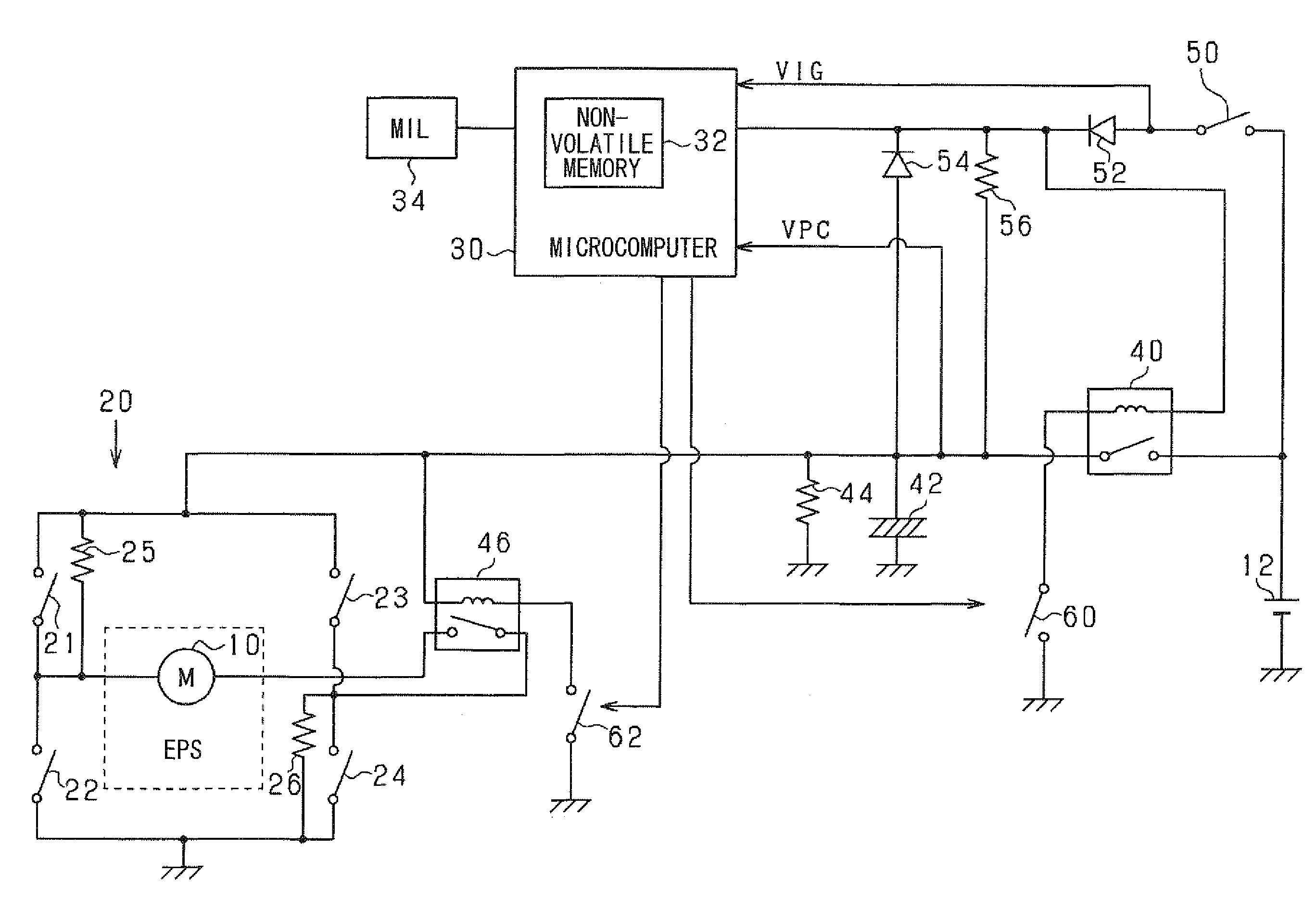
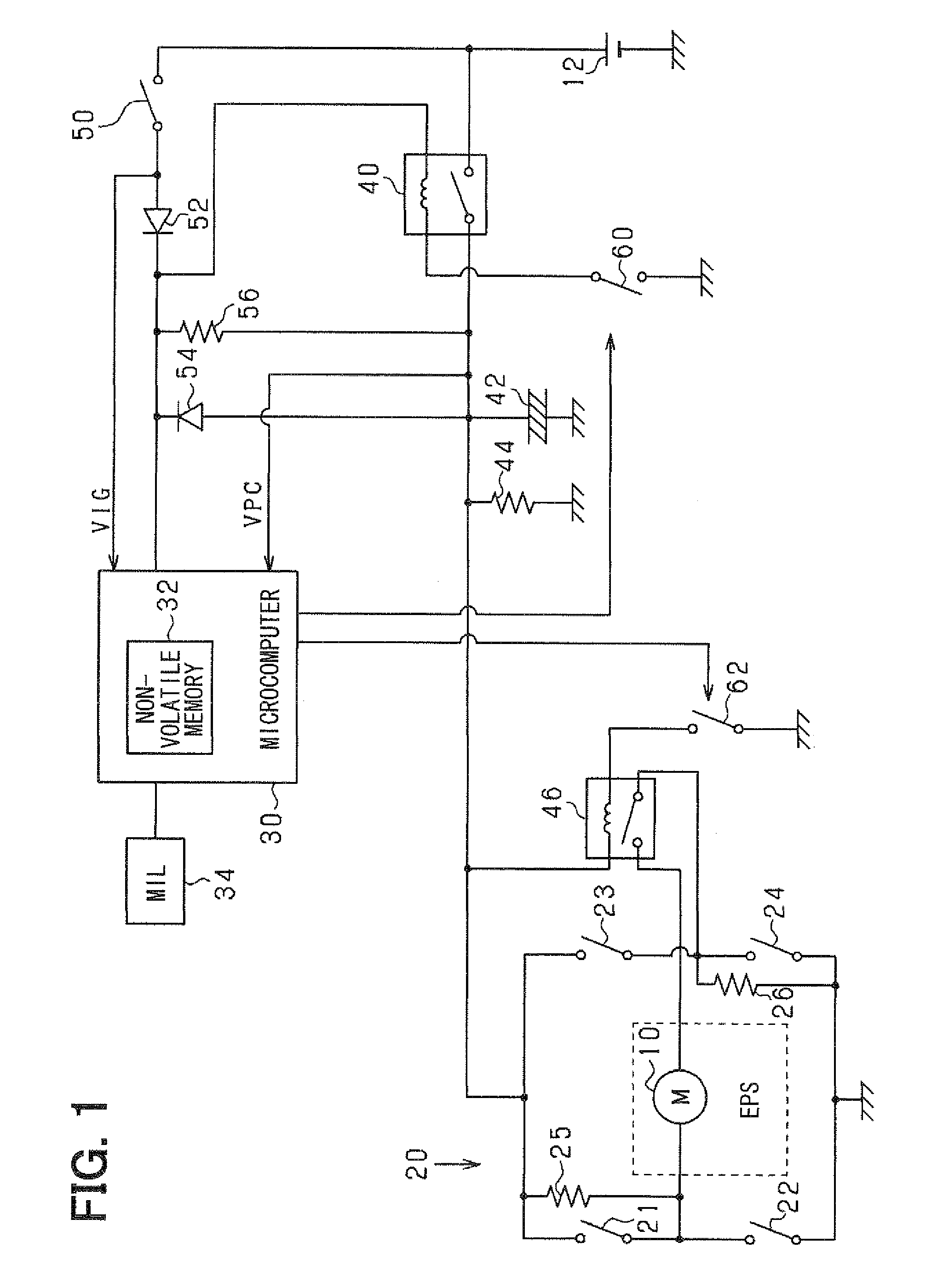
[0023]Referring to FIG. 1, an electric motor 10 is a DC motor with brushes. The motor 10 is an actuator provided in a steering apparatus, which power-assists steering operation of a driver. The motor 10 is supplied with electric power of a battery 12 through a H-bridge circuit 20.

[0024]The H-bridge circuit 20 is an electric power conversion circuit for supplying the electric power of the battery 12 to the motor 10. Specifically, the H-bridge circuit 20 has parallel-connected series arms. In one series arm, switching elements 21 and 22 are connected in series. In the other series arm, switching elements 23 and 24 are connected in series. The switching elements 21 to 24 may be transistors. A pair of terminals of the motor ...

second embodiment

[0052]A second embodiment is described next with respect to parts different from the first embodiment.

[0053]In the second embodiment, the power supply relay 40 is further diagnosed with respect to its fixed-open abnormality, in which the movable contact cannot be moved to close the input terminal and the output terminal in the power supply relay 40.

[0054]The principle of diagnosing the power supply relay 40 with respect to the fixed-open abnormality is shown in FIGS. 4A and 4B, in which the power supply relay 40 is assumed to be normal and abnormal, respectively. In FIGS. 4A and 4B, (a1) and (a2) indicate changes of the ignition switch 50, (b1) and (b2) indicate changes of the power supply relay 40, (c1) and (c2) indicate changes of the motor relay 46, (d1) and (d2) indicate changes of the output voltage VIG of the ignition switch 50, and (e1) and (e2) indicate changes of the charge voltage VPC of the capacitor 42.

[0055]If the power supply relay 40 is normal, as shown in FIG. 4A, wh...

third embodiment

[0064]A third embodiment is described next with respect to parts different from the second embodiment.

[0065]In the third embodiment, the abnormality diagnosis processing is executed as shown in FIG. 6 in response to the turn-on of the ignition switch 50 as a trigger. In FIG. 6, steps S60, S62, S64 and S66 are executed in addition to the steps executed in the second embodiment (FIG. 5).

[0066]If it is determined at step S42 that the fixed-closure abnormality is not present (NO), it is then checked at step S60 whether a predetermined time 13 has elapsed. The predetermined time 13 is set to correspond to a period required to charge the capacitor 42 to a predetermined voltage β by the ignition voltage VIG through the pre-charge resistor 56. If the predetermined time elapses (S62: YES), it is checked at step S62 whether the charge voltage VPC is greater than the predetermined voltage β. This step S62 is for checking whether the pre-charge path including the pre-charge resistor 56 has any ...


PUM


Abstract

In a power source circuit for supplying electric power of a battery, a capacitor is charged by the battery when an ignition switch and a power supply relay are closed. The power supply relay is opened after the ignition switch is closed. The charge voltage of the capacitor falls, if the power supply relay has no fixed-closure abnormality. The charge voltage of the capacitor does not fall, if the power supply relay has the fixed-closure abnormality. A microcomputer diagnoses the power supply relay with respect to its fixed-closure abnormality based on the charge voltage of the capacitor when the ignition switch and the power supply relay are operated to open.

Description

CROSS REFERENCE TO RELATED APPLICATION[0001]This patent application is based on and incorporates herein by reference Japanese Patent Applications No. 2008-261333 filed on Oct. 8, 2008 and No. 2008-286696 filed on Nov. 7, 2008.FIELD OF THE INVENTION[0002]The present invention relates to an electric power source circuit and an abnormality diagnosis system for the electric power source circuit. The electric power source circuit includes an power supply relay for opening and closing an electric power conversion circuit and an power supply part, a capacitor connected between an electric current path, which is formed between the power conversion circuit and the power supply relay, and a reference potential source, a pre-charge path bypassing the power supply relay for pre-charging the capacitor, and an on / off switch for connecting and disconnecting the pre-charge path and the power supply part.BACKGROUND OF THE INVENTION[0003]In a conventional electric power source circuit, an power suppl...

Claims


Application Information

Patent Timeline
IPC IPC(8): G01R31/02
CPCG01R31/3277H01H47/00G01R31/327G01R31/40
Inventor ICHIKAWA, KAZUHIROOOHASHI, YUTAKA
Owner DENSO CORP
Why Eureka
Try Eureka