
Reflector Array and Antenna Comprising Such a Reflector Array

a reflector array and reflector array technology, which is applied in the direction of slot antennas, antennas, electrical equipment, etc., can solve the problems of reducing the inability to calculate the electrical characteristics of the radiating elements assuming an infinite periodicity, and the inability to meet the requirements of the array antenna layout. , to achieve the effect of enhancing the directivity of the array antenna and reducing the disturbance of the radiation pattern

Active Publication Date: 2010-04-08
THALES SA
View PDF19 Cites 41 Cited by
  • Summary
  • Abstract
  • Description
  • Claims
  • Application Information

AI Technical Summary

Benefits of technology

[0007]The aim of the present invention is to remedy these drawbacks by proposing a reflector array that does not introduce strong breaks in the periodicity of the radiating elements on the reflecting surface and thus makes it possible to reduce the disturbances in the radiation pattern and enhance the directivity of the array antenna comprising such a reflector array.
[0008]Another aim of the invention is to propose a reflector array that makes it possible to reduce the number of transitions while increasing the possibilities of varying the phase of the waves reflected by the radiating elements.
[0009]A final aim of the invention is to propose a reflector array comprising individual radiating elements that have a simple and compact radiating structure.

Problems solved by technology

The lay-out of the radiating elements in the reflector array requires great attention.
However, the reflector arrays that are currently known present a major problem.
As a result of this, there are two problems: firstly, the standard approximation which consists in calculating the electrical characteristics of the radiating elements assuming an infinite periodicity is no longer valid for these elements.
This causes an increase in the level of the secondary lobes which, even it remains less than −20 dB, creates a degradation of the directivity of the associated antenna 10 which is unacceptable for a telecommunication antenna.

Method used


Image

  • Reflector Array and Antenna Comprising Such a Reflector Array
  • Reflector Array and Antenna Comprising Such a Reflector Array
  • Reflector Array and Antenna Comprising Such a Reflector Array

Examples


Embodiment Construction

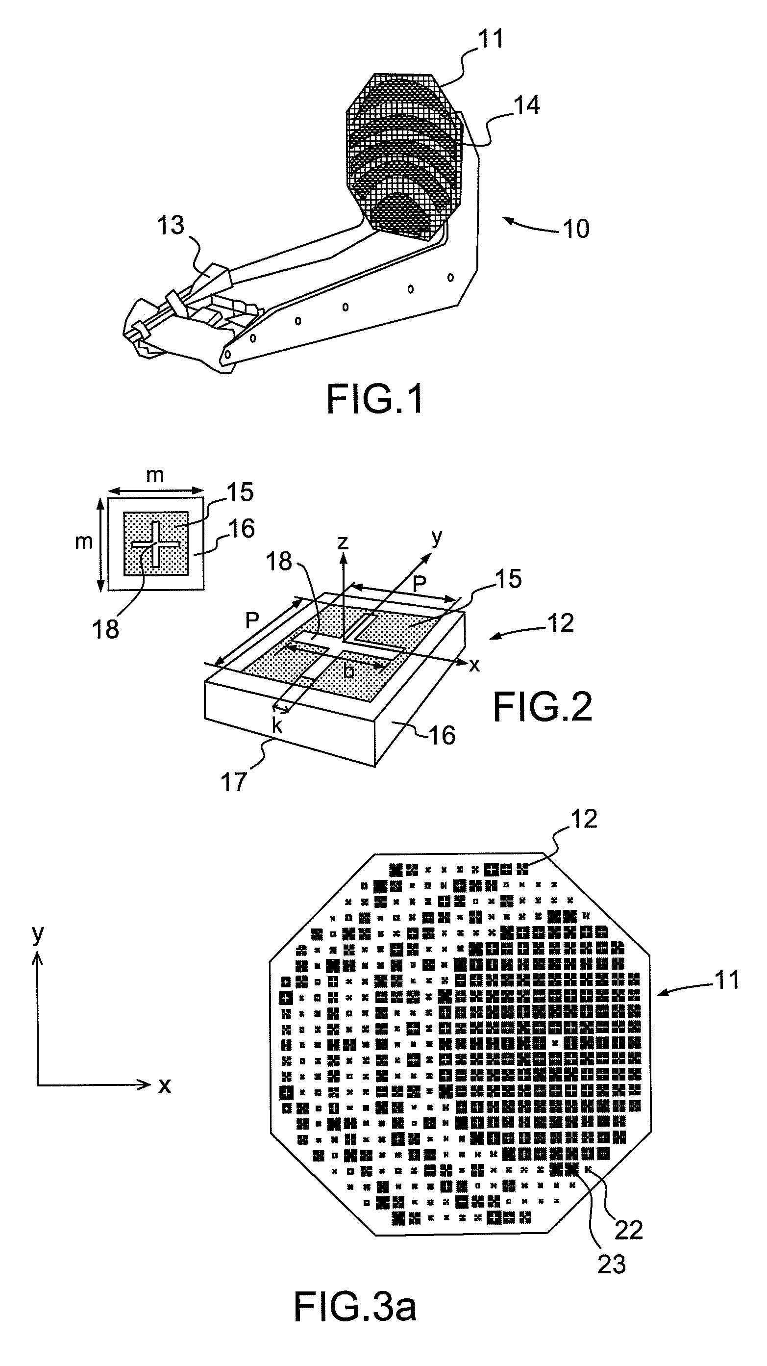
[0042]FIG. 1 shows an example of a reflector array antenna comprising an optimized reflector array 11, as described below, forming a periodic reflecting surface 14 and a primary feed 13 to illuminate the reflector array 11 with an incident wave.

[0043]FIG. 2 shows an example of a square shaped individual radiating element 12 that has sides of length m, comprising a metal patch 15 printed on a top surface of a dielectric substrate 16 provided with a metal ground plane 17 on its bottom face. The metal patch 15 has a square shape with sides of dimension p and includes two slots 18 of length b and of width k formed in its centre, the slots being arranged in the shape of a cross. In a three-dimensional coordinate system XYZ, the plane of the reflecting surface of the radiating element is the plane XY. The shape of the individual radiating elements 12 is not limited to a square; it can also be rectangular, triangular, circular, hexagonal, in the shape of a cross, or any other geometrical s...


PUM


Abstract

A reflector array comprises a plurality of individual radiating elements forming a reflecting surface with no abrupt transitions wherein each radiating element of the reflecting surface is selected from a set of predetermined consecutive radiating elements, called the pattern, the first and last elements of the pattern correspond to one and the same phase, modulo 360°, and are identical, and the radiating elements of the pattern have a radiating structure, of metal patch type and / or of radiating aperture type, that progressively changes from one radiating element to another adjacent radiating element, the change in the radiating structure comprising a succession of progressive growths of at least one metal patch and / or at least one aperture and appearances of at least one metal patch in an aperture and / or at least one aperture in a metal patch.

Description

CROSS-REFERENCE TO RELATED APPLICATIONS[0001]This application claims priority of French application no. FR 0805530, filed Oct. 7, 2008, the disclosure of which is hereby incorporated by reference in its entirety.FIELD OF THE INVENTION[0002]The present invention relates to a reflector array for a reflector array antenna. It applies notably to antennas mounted on a spacecraft such as a telecommunication satellite or to the antennas of terrestrial terminals for satellite telecommunication or broadcasting systems.BACKGROUND OF THE INVENTION[0003]A reflector array (or “reflectarray”) antenna 10, as represented for example in FIG. 1, comprises a set of individual radiating elements 12 assembled in a one- or two-dimensional array 11 and forming a reflecting surface 14 making it possible to increase the directivity and the gain of the antenna 10. The individual radiating elements, also called individual cells, of the reflector array, of metal patch and / or slot type, have variable parameters...

Claims


Application Information

Patent Timeline
IPC IPC(8): H01Q15/14
CPCH01Q3/46H01Q15/002H01Q21/061H01Q19/104H01Q21/00H01Q13/10H01Q19/10
Inventor LEGAY, HERVEBRESCIANI, DANIELECHINIARD, RENAUDGIRARD, ETIENNE
Owner THALES SA
Learn More