Illumination Sources and Customizable Spectral Profiles

a technology of illumination sources and spectral profiles, applied in the field of optics, spectroscopy, and illumination sources, to achieve the effects of reducing power on a target, reducing power consumption, and maximizing spectral distribution

Inactive Publication Date: 2010-04-08
BOARD OF RGT THE UNIV OF TEXAS SYST
View PDF13 Cites 9 Cited by
  • Summary
  • Abstract
  • Description
  • Claims
  • Application Information

AI Technical Summary

Benefits of technology

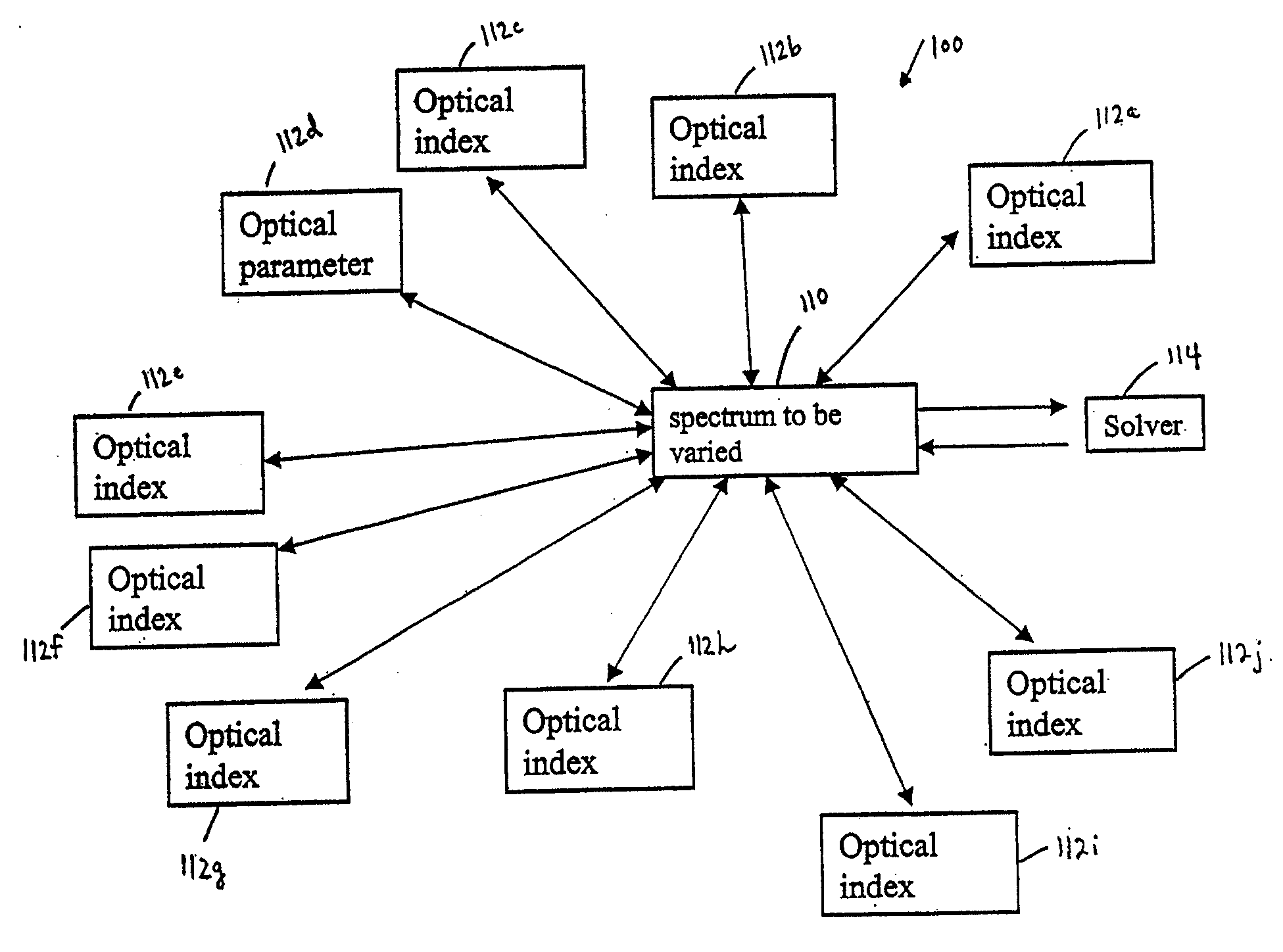
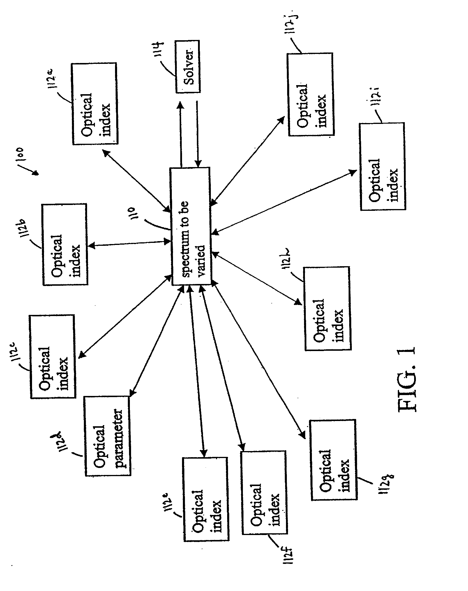
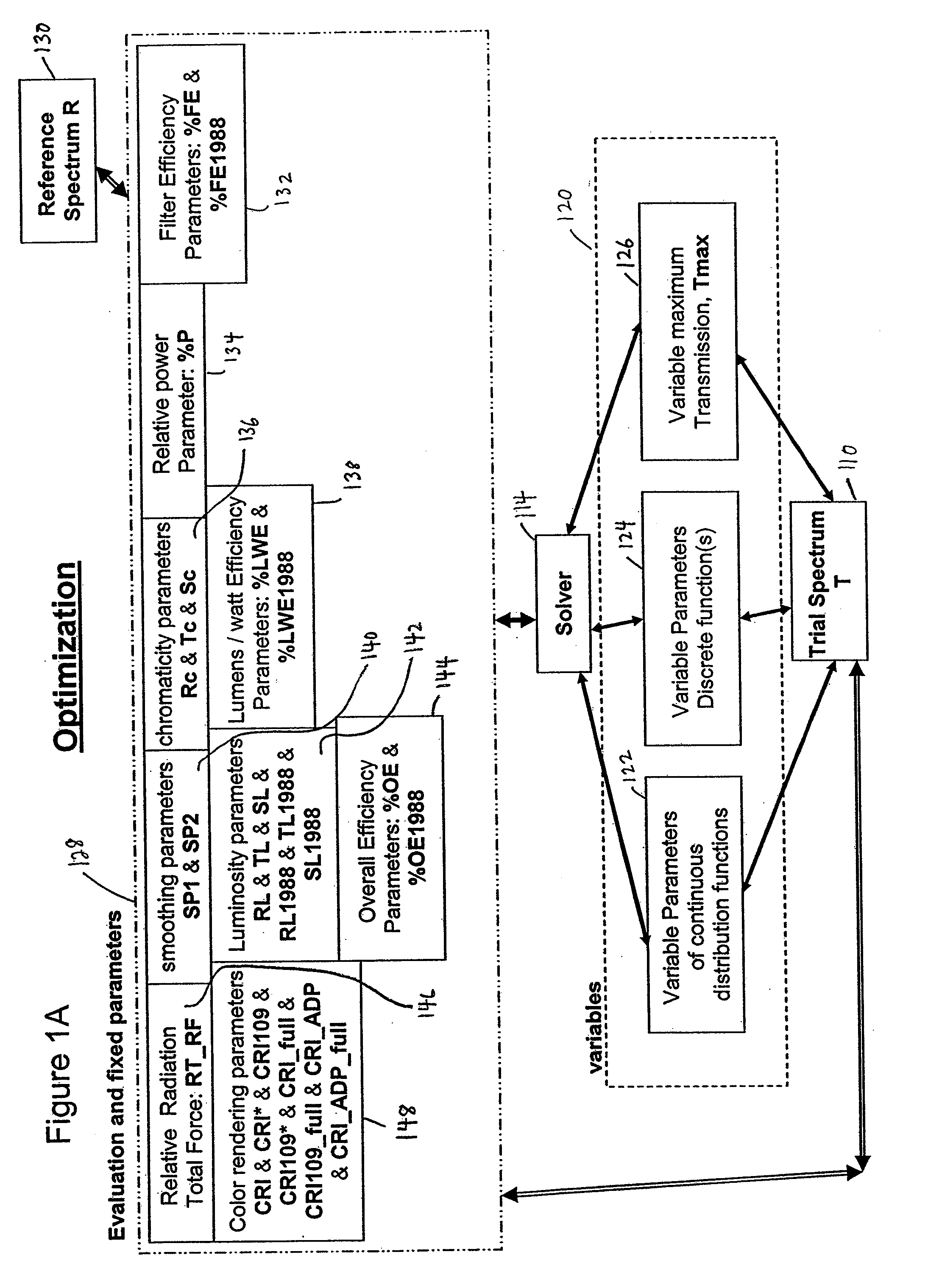
[0015]Lumens / watt efficiency—This parameter can assure that total power on a target is reduced relative to luminosity produced;
[0020]1) The CIE 13.3 theory has been modified. This modification involves incorporation of a more modern adaptive color correction (ADC) to the color rendering index (CRI or CRI*). In one embodiment, this more modern ADC can be based on CIE 109, published about 1995. The original ADC built into CIE 13.3 is based on a theory from before 1900. In this disclosure, the modified CRI parameter is called “CRI109” (or CRI109*, which matches the terminology scheme used in the previous disclosure to indicate a modification based on real data from works of art or other objects. As those having ordinary skill in the art will recognize with the benefit of this disclosure, utilizing CRI109 can provide more flexibility. One can, for instance, more reliably optimize to spectral distributions that differ in color temperature (CT). The original CIE 13.3 method is not always suitable for optimizing far-off the CT of a reference or when one deviates significantly from Planckian blackbody distributions. This is due to the relatively primitive ADC built into the CIE 13.3 theory. Use of CRI109 provides more robustness to calculations of arbitrary distributions used in this disclosure. Moreover, the CIE 109 ADC theory varies with luminance on target, so adjustments can be made to control the effect of lighter or darker illuminations on CRI (or CRI*), as necessary. This, in turn, can be useful unto itself since one may need to optimize to specific lighting level conditions (e.g., 50 lux, 75 lux, 150 lux, etc.). CRI109 varies from 50-150 lux, and the standard method (CIE 13.3) doesn't see this effect.
[0021]2) Another modification entails reducing power on a target while maintaining luminance. This can be achieved to some degree using techniques of the previous disclosure; however, in some embodiments of the previous disclosure, one may “pile up” light in other spectral regions above the level of standard lamps. One may think that as long as power is being reduced, the end-effect is beneficial. But, depending on the energy of the light that is being piled-up, one may potentially create a different, harmful situation. An extreme example showing potential harm is revealed through comparison with a laser: all the power is piled into one narrow energy band and the laser can do damage at that energy because of this. By piling power up too much, one heads toward the extreme of that situation. The inventor has found that a solution to this scenario is to optimize away from it: i.e. optimize one or more parameters in order to avoid potentially-harmful energy pile-up. As this disclosure discusses in more detail below, one can create a new parameter, which is the power times the energy. This parameter has units of force, and in this disclosure it is called the Radiation Force (RF) parameter. The parameter can be implemented several ways. For example, one may sum the total RF across the spectrum and relate this to the total RF across a reference lamp to get a total relative RF (TRRF). In a representative embodiment, one wants to reduce power, making sure that the TRRF goes down. The two track in some way, but minimums in power do not necessarily lead to minimums in TRRF, and the reverse is true as well. Additionally, use of another new parameter can be beneficial: the relative RF (or, “RRF,” which should be distinguished from the TRRF). RRF is able to indicate radiation force at specific wavelengths or in specific spectral regions. In different embodiments, one can minimize or optimize RRF in certain spectral regions to further ensure that harmful pile-up does not occur. Although one can design a filter or illuminant that reduces power without using these new parameters, use of the new parameters can lead to a better solution. Particularly, a solution can be fashioned that is safer and does not create potentially harmful light / energy pile-up at different portions of a spectrum.
[0034]The customized spectral profile can be such that it renders only photometric light, or tailored regions of photometric light. The spectral profile can be such that it aesthetically renders an object. The customized spectral profile can be, for example, a candlelight profile that can render the object as if illuminated by candlelight. Additionally or alternatively, the customized spectral profile can be a torchlight profile that can render the object as if illuminated by torchlight, a fluorescent profile that can render the object as if illuminated by fluorescent lighting, an incandescent profile that can render the object as if illuminated by incandescent profile, a halogen profile that can render the object as if illuminated by halogen-based lighting, an oil lamp profile that can render the object as if illuminated by an oil lamp, a daylight profile that can render the object as if illuminated by sunlight, a roomlight profile that can render the object as if illuminated by sunlight or candlelight scattered in a room, a gas light profile that can render the object as if illuminated by a gas light, a lime light profile that can render the object as if illuminated by a lime light, and / or a mantle-light profile that can render the object as if illuminated by a Welsbach mantle.
[0040]In another embodiment, the invention involves the ability to optimize an optical filter that will not have unsafe spectral concentrations of light while reducing the overall power of the filter. This can be accomplished with a parameter which weights the energy of a spectral portion of light with its power.
[0043]In another embodiment, the invention involves techniques for the smoothing a tailored trial spectrum while maintaining other advantageous spectral parameters to render a more easily manufactureable optical filter.

Problems solved by technology

1) The CIE 13.3 theory has been modified. This modification involves incorporation of a more modern adaptive color correction (ADC) to the color rendering index (CRI or CRI*). In one embodiment, this more modern ADC can be based on CIE 109, published about 1995. The original ADC built into CIE 13.3 is based on a theory from before 1900. In this disclosure, the modified CRI parameter is called “CRI109” (or CRI109*, which matches the terminology scheme used in the previous disclosure to indicate a modification based on real data from works of art or other objects. As those having ordinary skill in the art will recognize with the benefit of this disclosure, utilizing CRI109 can provide more flexibility. One can, for instance, more reliably optimize to spectral distributions that differ in color temperature (CT). The original CIE 13.3 method is not always suitable for optimizing far-off the CT of a reference or when one deviates significantly from Planckian blackbody distributions. This is due to the relatively primitive ADC built into the CIE 13.3 theory. Use of CRI109 provides more robustness to calculations of arbitrary distributions used in this disclosure. Moreover, the CIE 109 ADC theory varies with luminance on target, so adjustments can be made to control the effect of lighter or darker illuminations on CRI (or CRI*), as necessary. This, in turn, can be useful unto itself since one may need to optimize to specific lighting level conditions (e.g., 50 lux, 75 lux, 150 lux, etc.). CRI109 varies from 50-150 lux, and the standard method (CIE 13.3) doesn't see this effect.

Method used


Image

  • Illumination Sources and Customizable Spectral Profiles
  • Illumination Sources and Customizable Spectral Profiles
  • Illumination Sources and Customizable Spectral Profiles

Examples


Embodiment Construction

[0063]In general, the present invention provides techniques for generating customized spectral profiles, which can be used to generate corresponding optical filters, lamps or other illuminants customized to a spectral profile. Representative embodiments relate to spectral profiles that may be used to generate optical filters, lamps, or other types of illuminants that (a) protect objects such as works of art, (b) aesthetically render objects, and / or (c) correct the rendering of an object. Other uses of the spectral profiles will be apparent to those of ordinary skill in the art, having the benefit of this disclosure.

[0064]Custom spectral profiles may be created according to a particular visualization application. Once the custom spectral profile is created, a corresponding filter, lamp, or other illuminant can be built to realize that spectral profile. This filter could be of the interference type, the absorptive loss type, or a combination of these types. Different visualization app...


PUM


Abstract

Methods for generating a customized spectral profile, which can be used to generate a corresponding filter, lamp or other type of illuminant. A trial spectrum can be generated. A reference spectrum can be determined or otherwise obtained. A SOURCE spectrum can be determined or otherwise obtained. One or more optical indices can be calculated using the trial spectrum and one or more of the optical indices are optimized by varying the trial spectrum to generate the customized spectral profile. A radiation force parameter can be used to minimize unsafe build-up of light in spectral regions. Adaptations of color rendering parameters can be used in the optimization process. Smoothing parameters can be used to enable easier design of filter structures. A reflectance camera can be used to measure reflectance data at one or more pixels of a digital representation of an object to be illuminated.

Description

[0001]This application is a continuation of, claims priority to, and incorporates by reference, U.S. patent application Ser. No. 11 / 232,442, filed Sep. 21, 2005; and claims priority to, and incorporates by reference, U.S. Provisional Patent Application Ser. No. 60 / 612,309, which was filed Sep. 22, 2004.[0002]This application incorporates by reference U.S. patent application Ser. No. 10 / 688,200 entitled “Customizable Spectral Profiles for Filtering,” by Carl W. Dirk, which was filed on Oct. 17, 2003.BACKGROUND OF THE INVENTION[0003]1. Field of the Invention[0004]The present invention relates generally to optics, spectroscopy, and illumination sources. More particularly, the present invention relates to techniques for generating customized spectral profiles, which can be used to generate corresponding optical filters, lamps, or illuminants that have a particular spectral profile as a feature. Representative embodiments relate to spectral profiles that may be used for (a) protecting wo...

Claims


Application Information

Patent Timeline
Patent Type & Authority Applications(United States)
IPC IPC(8): G01J3/00
CPCG01J3/10G01J3/46G01J3/462G02B27/0012G01J2001/0276G01J2003/1282G01J3/465
Inventor DIRK, CARL W.
Owner BOARD OF RGT THE UNIV OF TEXAS SYST
Why Eureka
Try Eureka