Fiber optic network installation

Active Publication Date: 2010-04-08
TERASPAN NETWORKS
View PDF11 Cites 41 Cited by
  • Summary
  • Abstract
  • Description
  • Claims
  • Application Information

AI Technical Summary

Benefits of technology

[0023]Objects of this invention include providing improved systems and methods for storing and routing fibre optic cables through branched substrate channels, to provide a convenient cable network branching system and to accommodate future expansion of the network. The present invention takes advantage of the fact that, in many cases, one may predict at the time of initially installing cable trunk lines the general location of at least some future branches. For example, when installing trunk

Problems solved by technology

A challenge faced by the telecommunications industry is the high cost of installing optical fibre between the provider and the end customer.
Some of the highest costs are incurred in the so-called “last mile” of installation, namely the installation of lines to individual customers and limited groups of customers, often within urban areas.
In particular, as customers are added to a network, the generation of a new branch line can be difficult and costly, often requiring the installer to make a splice or junction with the trunk line and to provide loops of surplus cable at predetermined locations in advance when installing the initial trunk lines.
Optical cables are typically buried, which can present difficulties when it is desired to expand a network.
However, it can be difficult to conveniently store suitable lengths of dark line within the network

Method used


Image

  • Fiber optic network installation
  • Fiber optic network installation
  • Fiber optic network installation

Examples


Example

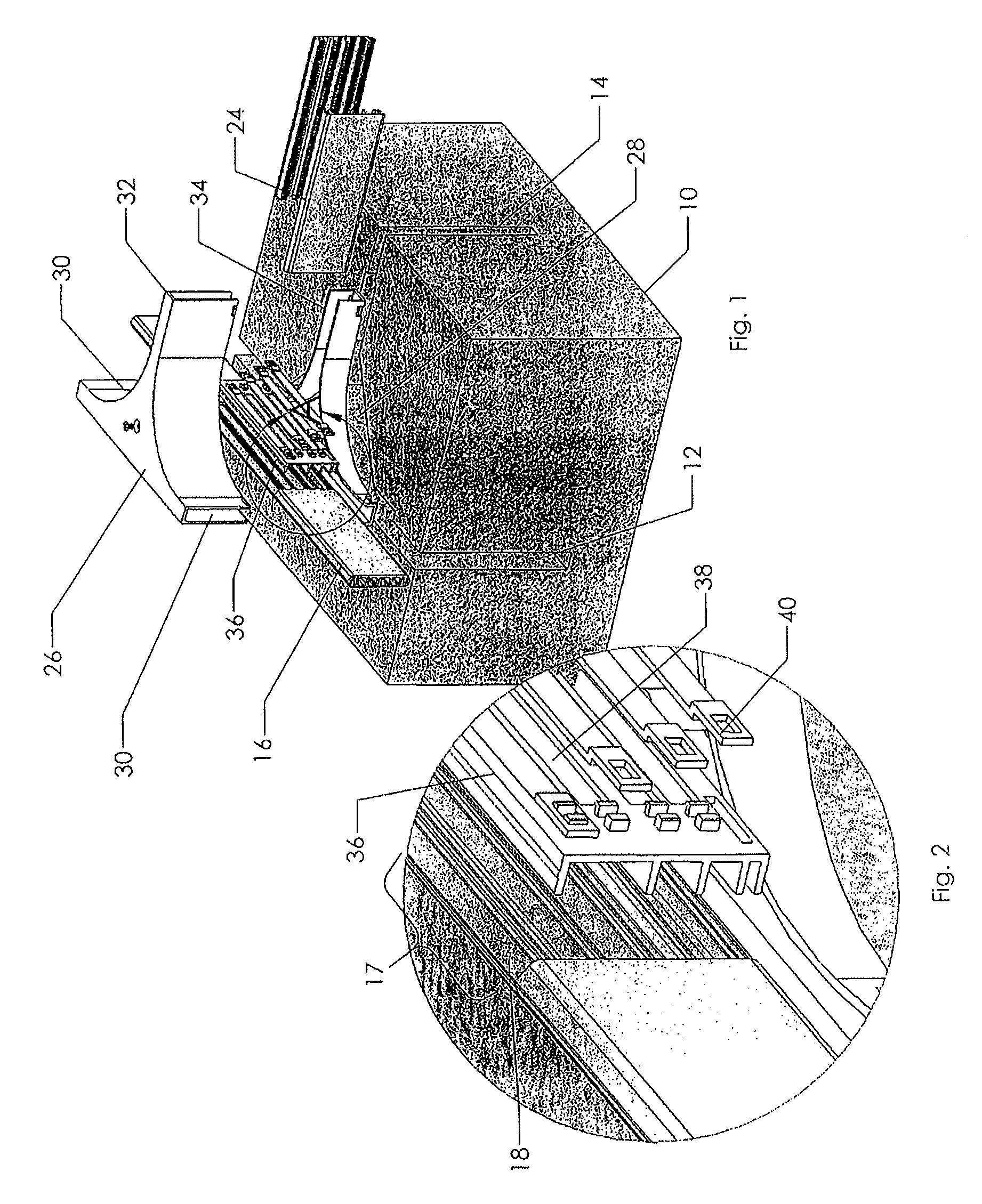
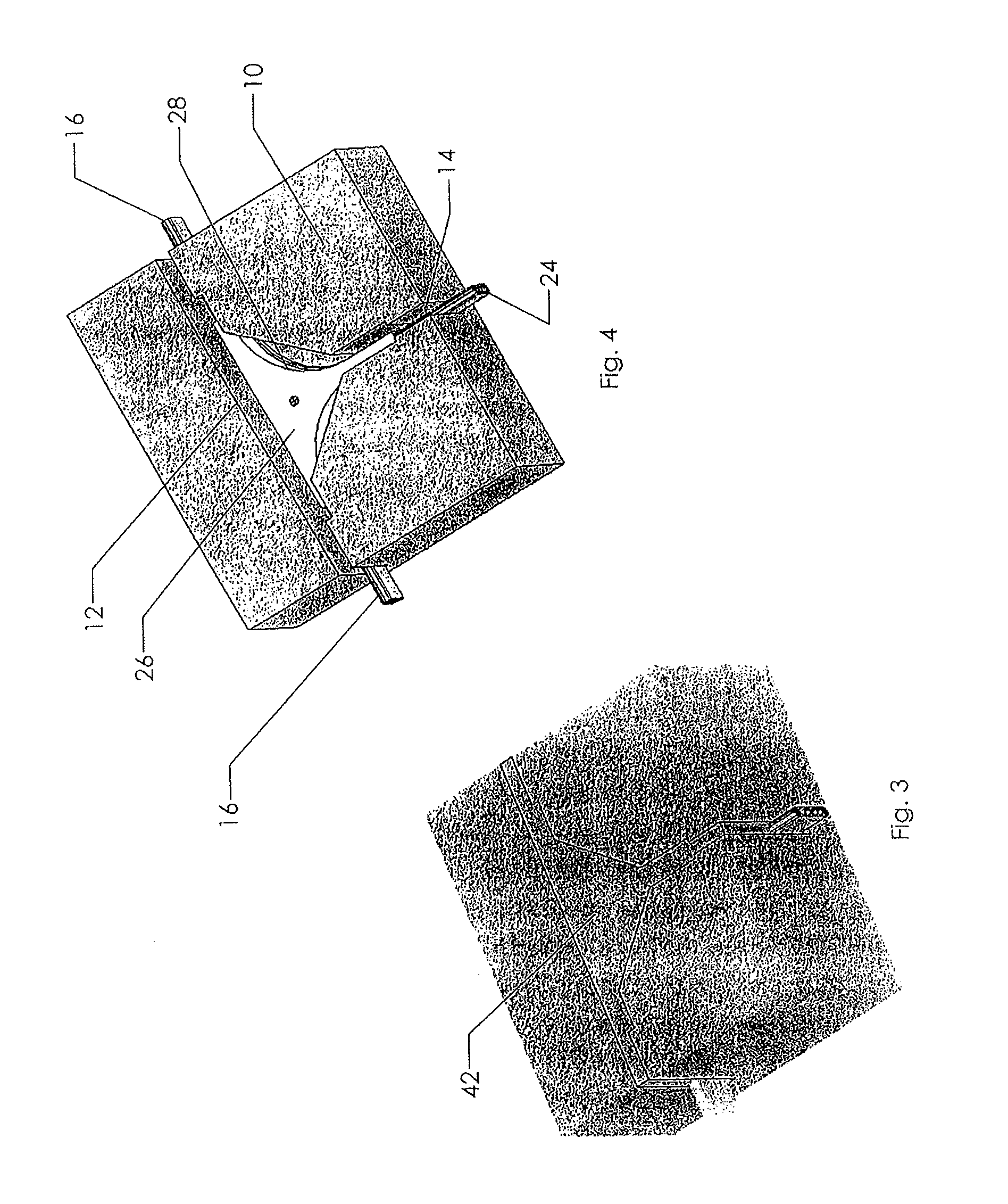
[0053]According to one embodiment shown in FIGS. 1-5, the initial stage of installing the system according to one aspect of the invention involves cutting a primary or trunk channel 12 within a substrate 10. The substrate 10 may consist of essentially any surface including a road surface, a walkway, sidewalk, masonry wall or the like. The surface may be a hard surface or a soft surface such as turf. The channel 12 is narrow and may be conveniently formed by making a single pass of a slab saw. A primary fibre optic cable conduit 16 is inserted into the channel 12. The installer must determine the location or locations of expected branch points in the network where future (or present) expansion may be forthcoming, for example where a new house or building is planned and it is possible that a cable branch will be required. At this junction location, a segment of one wall of the primary fibre optic cable conduit is removed to form a gap 17 in the conduit wall so as to expose the interio...


PUM


Abstract

A fibre optic network system for a multi-staged installation to a plurality of present and future user locations includes an aggregation point, a trunk line with a plurality of optic fibre cables leading from the aggregation point and at least one branch junction location to serve a future cable user. The trunk line includes at least one dark cable having a free end for removal from the branch junction location. The trunk line includes a trunk conduit having opposing side walls defining an interior space between the side walls for housing the cables. The conduit is configured to permit withdrawal of the length of dark cable from the conduit at a stage subsequent to installation of the trunk line to form a branch leading to the future user location. The dark cable stored within the interior of the conduit has sufficient length to reach the location of the future user.

Description

PRIORITY STATEMENT[0001]This application claims the benefit of priority to U.S. Provisional Application Ser. No. 60 / 916,078 filed May 4, 2007, which is incorporated herein by reference in its entirety.FIELD OF THE INVENTION[0002]The present invention relates to fibre optic networks, in particular fibre optic networks buried below a surface, wherein the fibre optic cables and fibres are protected from the elements by an external duct or conduit. The invention relates to systems, apparatus and methods for providing a fibre optic network.BACKGROUND OF THE INVENTION[0003]A challenge faced by the telecommunications industry is the high cost of installing optical fibre between the provider and the end customer. Some of the highest costs are incurred in the so-called “last mile” of installation, namely the installation of lines to individual customers and limited groups of customers, often within urban areas. In particular, as customers are added to a network, the generation of a new branc...

Claims


Application Information

Patent Timeline
IPC IPC(8): G02B6/46G02B6/26G02B6/28
CPCG02B6/504
Inventor DOFHER, DARREN
Owner TERASPAN NETWORKS
Why Eureka
Try Eureka