

Optical connector
- Summary
- Abstract
- Description
- Claims
- Application Information
AI Technical Summary
Benefits of technology
Problems solved by technology
Method used
Image

Examples
first embodiment
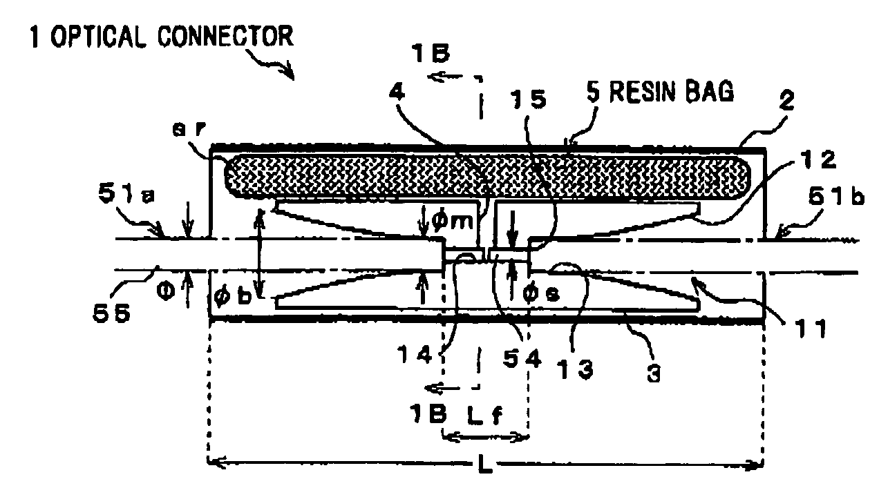
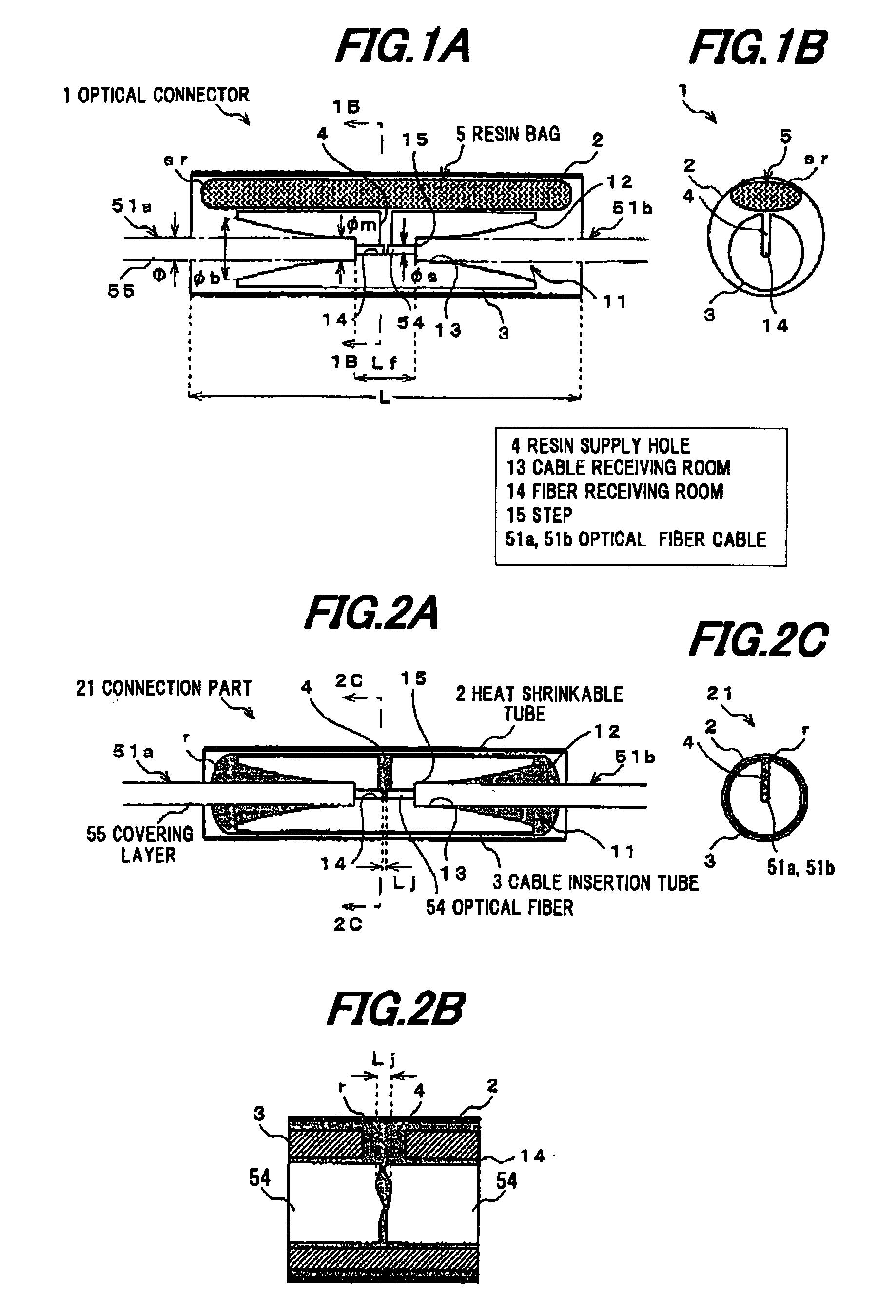
[0035]The first preferred embodiment of the invention will be explained below referring to the drawings.
[0036]FIG. 5 is a cross sectional view showing an example of an optical fiber cable to be connected by an optical connector in the embodiments of the invention.
[0037]As shown in FIG. 5, an optical fiber cable 51 is constructed of an optical fiber (or optical fiber core) 54 composed of a core 52 and a cladding 53 covering the periphery of the core 52, and a covering layer 55 covering the periphery of the optical fiber 54. In this embodiment, as the optical fiber 54, a single-mode optical fiber is used that is generally in wide use, mainly formed of silica glass, and 125 A m in outside diameter φ. The core 52 is about 1.463 in refractive index by adding a refractive index adjuster such as Ge into pure silica. The cladding 53 is formed of pure silica and 1.458 in refractive index.
[0038]The covering layer 55 is composed of an inner covering layer (or primary layer) 55a as a buffer lay...
second embodiment
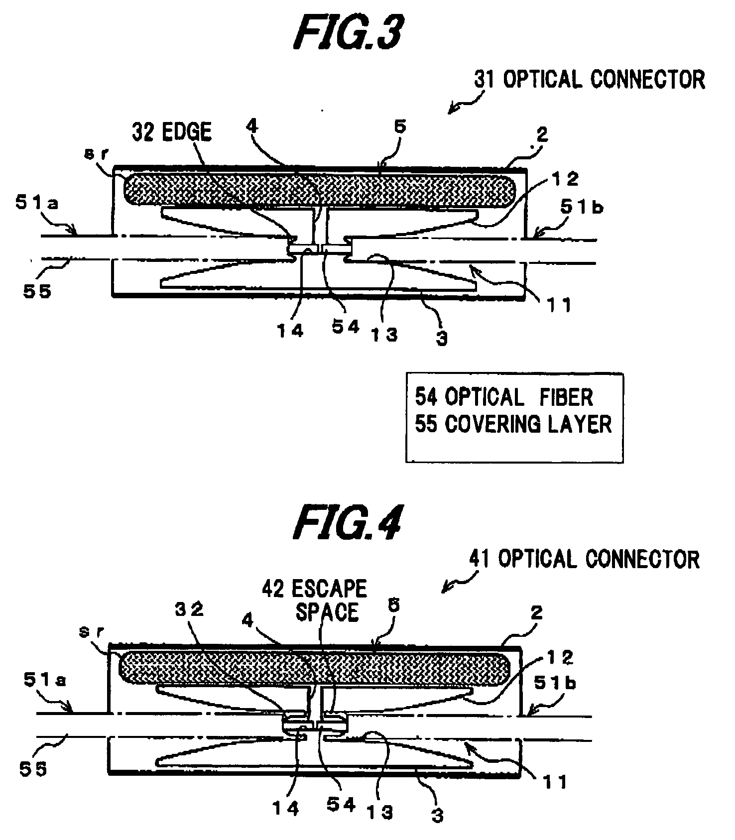
[0078]The second preferred embodiment of the invention will be explained below referring to FIG. 3.
[0079]As shown in FIG. 3, an optical connector 31 of the second embodiment is constructed such that, adding to the construction of the optical connector 1 in FIG. 1A, a sharp circular edge (blade) 32 is provided at the boundary of the cable receiving room 13 and the fiber receiving room 14 as a covering removal member for removing the covering layer 55 of the optical fiber cables 51a, 51b being inserted into the cable insertion tube 3 Therefore, the optical connector 31 does not need the additional step of removing the covering layer 55 of the optical fiber cables 51a, 51b since the covering layer 55 can be automatically and securely removed simultaneously when the optical fiber cables 51a, 51b are inserted into the cable insertion tube 3.
third embodiment
[0080]The third preferred embodiment of the invention will be explained below referring to FIG. 4.
[0081]As shown in FIG. 4, an optical connector 41 of the third embodiment is constructed such that, adding to the construction of the optical connector 31 in FIG. 3, a circular escape space 42 is provided around the axis of the fiber receiving room 14 to communicate the cable receiving room 13 with the insertion direction of the optical fiber cables 51a, 51b for allowing the escape or accommodation of the removed (or peeled) secondary layer 55b.
[0082]In the optical connector 41, the removed covering layer 55 is automatically shrunk or received in the escape space 42 when the optical fiber cables 51a, 51b are inserted into the cable insertion tube 3.
[0083]Therefore, the optical connector 41 allows further simplification of the connection work and further lowering in eccentricity of the optical fibers 54a, 54b.
[0084]In the above embodiments, the resin bag 5 is exemplarily enclosed in th...
PUM
| Property | Measurement | Unit |
|---|---|---|
| Temperature | aaaaa | aaaaa |
| Diameter | aaaaa | aaaaa |
| Refractive index | aaaaa | aaaaa |
Abstract
Description
Claims
Application Information