
System for impelling a fluid by recirculation from a low-pressure medium to a high-pressure medium

Inactive Publication Date: 2010-04-08
HYNERGREEN TECH
View PDF13 Cites 11 Cited by
  • Summary
  • Abstract
  • Description
  • Claims
  • Application Information

AI Technical Summary

Benefits of technology

[0002]The system finds special application in processes of heat exchange and gas dissolution, and also in processes of purification and desalination of water by reverse osmosis, and in general in all processes where its use is feasible and allows the energy consumption to be reduced.

Problems solved by technology

The advantage of rotary recirculators lies in their relative compactness, though on the other hand they have the drawbacks of high price and low efficiency, all the more so in the case in which the flow to duct and the working pressures are not constant but instead vary as a function of consumption requirements.
Since the machines are far from their theoretical functioning point, their efficiency, which is in any case limited, is notably reduced, with which their possibilities of energy recovery are very low.
Moreover, it is wished that the sealing between the chambers should be as perfect as possible, since, in addition to implying a waste of energy on account of its irreversibility and the consequent increase in entropy this implies, the connections between fluids at different pressures can also produce flooding and dangerous situations in a submarine.
Furthermore, in order to achieve a good efficiency the pressures of the two fluids in contact via the moving wall have to be the same, therefore, as is logical, the sliding of the piston has to be smooth and free of resistance due to friction, which is incompatible with being watertight.
This requisite, which is easy to achieve when dealing with fairly non-aggressive fluids such as mineral oil or even freshwater, represents a serious obstacle when the fluid to duct is saltwater, all the more so if it contains suspended particles of organic or mineral origin, which, due to their abrasive effect, rapidly deteriorate the interior of the jacket, at the same time damaging the seals of the piston.
The abrasive effects of the suspended matter can only be alleviated by means of careful filtration, which implies an added cost and consumes part of the available pressure in the form of load loss.
The advantage of the linear recirculators lies, therefore, in their acceptable efficiency, though nevertheless presenting the drawback that they require an almost continual need for maintenance.

Method used


Image

  • System for impelling a fluid by recirculation from a low-pressure medium to a high-pressure medium
  • System for impelling a fluid by recirculation from a low-pressure medium to a high-pressure medium
  • System for impelling a fluid by recirculation from a low-pressure medium to a high-pressure medium

Examples


Embodiment Construction

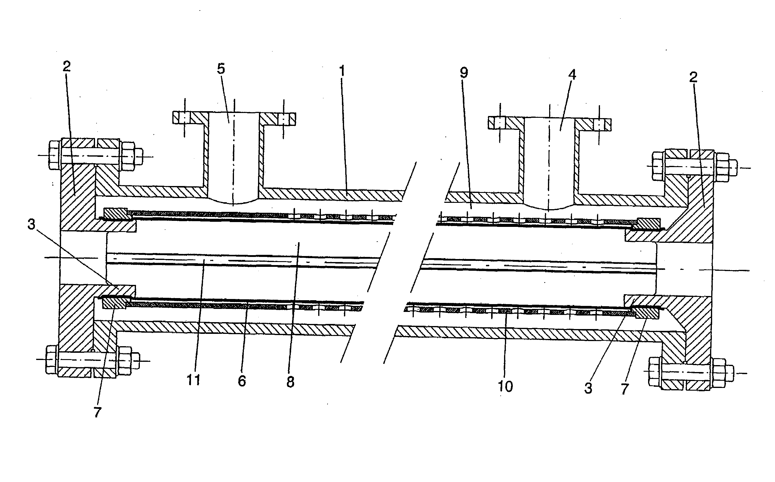
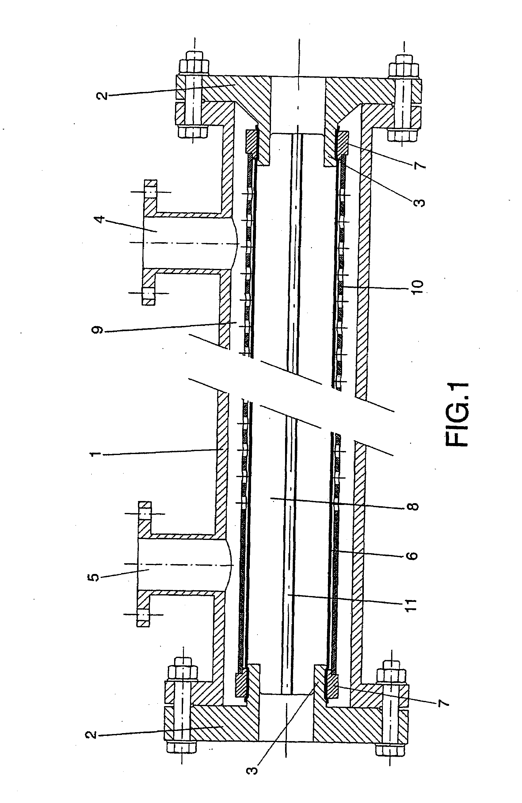
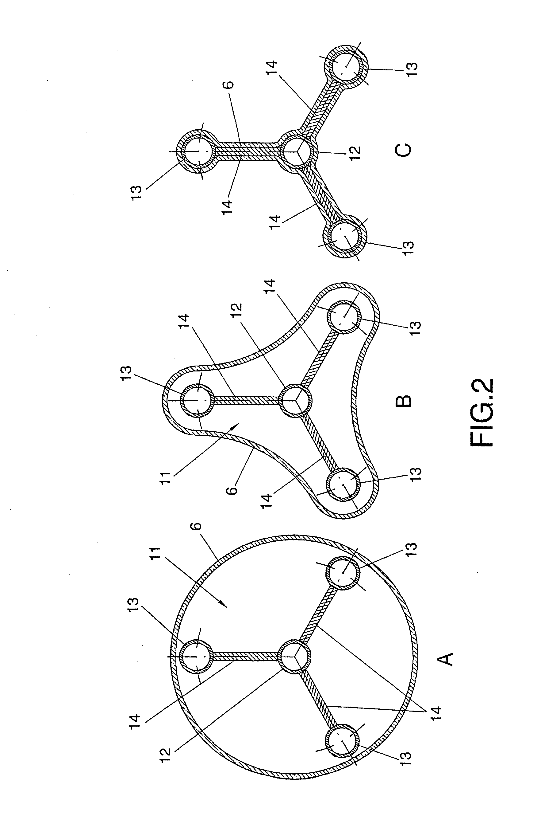
[0016]The system forming the object of the invention is conceived for solving the problems and drawbacks referred to above, being of the type that uses a moving wall recirculator, which presents the particular feature of being materialized by a flexible membrane, with a tubular and elongated configuration.

[0017]The said special recirculator is constituted on the basis of a tubular cylindrical body, straight and elongated, with intake and outlet that are opposite and differentiated, permitting the direction of circulation of the fluid and its quantity of movement to be conserved. Said body of the recirculator is provided at its ends with each of the removable bridles for permitting the inspection and replacement of the flexible membrane. One or two flanged intakes, preferably though not in a limiting way located at the ends, linked with a chamber exterior to the membrane, permit the utilization, indifferently, of two-way or three-way valves.

[0018]In terms of the flexible membrane whi...


PUM

PropertyMeasurementUnit
Pressureaaaaaaaaaa

Abstract

The system comprises a cylindrical recirculator (1), with a membrane concentrically fitted therein (6) for defining two chambers, one front chamber (8) and another outer one (9), in such a way that fluid flowing into either chamber causes expansion or constriction of the actual membrane (6) and corresponding impelling of the fluid, all this associated with a set of intake and impeller valves (16′), in combination with intake pumps (33) and impeller pumps (37) and check valves (34) and (35), whereby the fluid is impelled from the intake (31) towards the recirculator (1), so that the fluid flows from the recirculator to a reactor (32) and back again to the recycler (1) for the ejection of the processed fluid through the discharge conduit (36).

Description

OBJECT OF THE INVENTION[0001]As stated in the title of this descriptive specification, the present invention relates to a system for impelling a fluid by recirculation from a low-pressure medium to a high-pressure medium, the process being carried out with recovery of the energy contained in the fluid at high pressure in order to aid pumping from low pressure to high pressure, thereby achieving a reduction in the energy contribution required.[0002]The system finds special application in processes of heat exchange and gas dissolution, and also in processes of purification and desalination of water by reverse osmosis, and in general in all processes where its use is feasible and allows the energy consumption to be reduced.BACKGROUND OF THE INVENTION[0003]In accordance with the principles of physics, the pumping of a fluid from a low-pressure medium to a high-pressure medium requires an energy contribution directly proportional to the flow being ducted and to the difference in pressure...

Claims


Application Information

Patent Timeline
IPC IPC(8): F04B43/08B01D61/06B01D35/157
CPCB01D61/06F04B43/113B01D2317/04F04B43/10F04F13/00F04B43/00F15B15/00
Inventor DEL POZO POLIDORO, ENRIQUEGARCIA-ORTA, VICTORIA GALLARDOBREY SANCHEZ, JOSE JAVIER
Owner HYNERGREEN TECH
Learn More