Control of sequential downshifts in a transmission

Active Publication Date: 2010-04-08
FORD GLOBAL TECH LLC
View PDF5 Cites 6 Cited by
  • Summary
  • Abstract
  • Description
  • Claims
  • Application Information

AI Technical Summary

Benefits of technology

[0009]With this control strategy, there is no need to precisely synchronize the oncoming element of the first shift with the offgoing element of the second shift. Shift time is equivalent to that of a 6-2 direct downshift, providing greater consistency among the power on downshifts.
[0010]The control maintains output torque during the ratio change and allows for change of mind to the intermediate gear. Should the driver tip out early enough in the shift, the first oncoming element is applied and the second shift is cancelled. In addition, the final on coming element may be pre-staged to allow a continuous ratio change if the driver tips into a 6-4 or 5-3 downshift in progress.
[0011]Early application of the second on-coming element increases energy dissipation. The time the clutch applied, however, is significantly less than dur

Problems solved by technology

Early application of the second on-comi

Method used


Image

  • Control of sequential downshifts in a transmission
  • Control of sequential downshifts in a transmission
  • Control of sequential downshifts in a transmission

Examples


Embodiment Construction

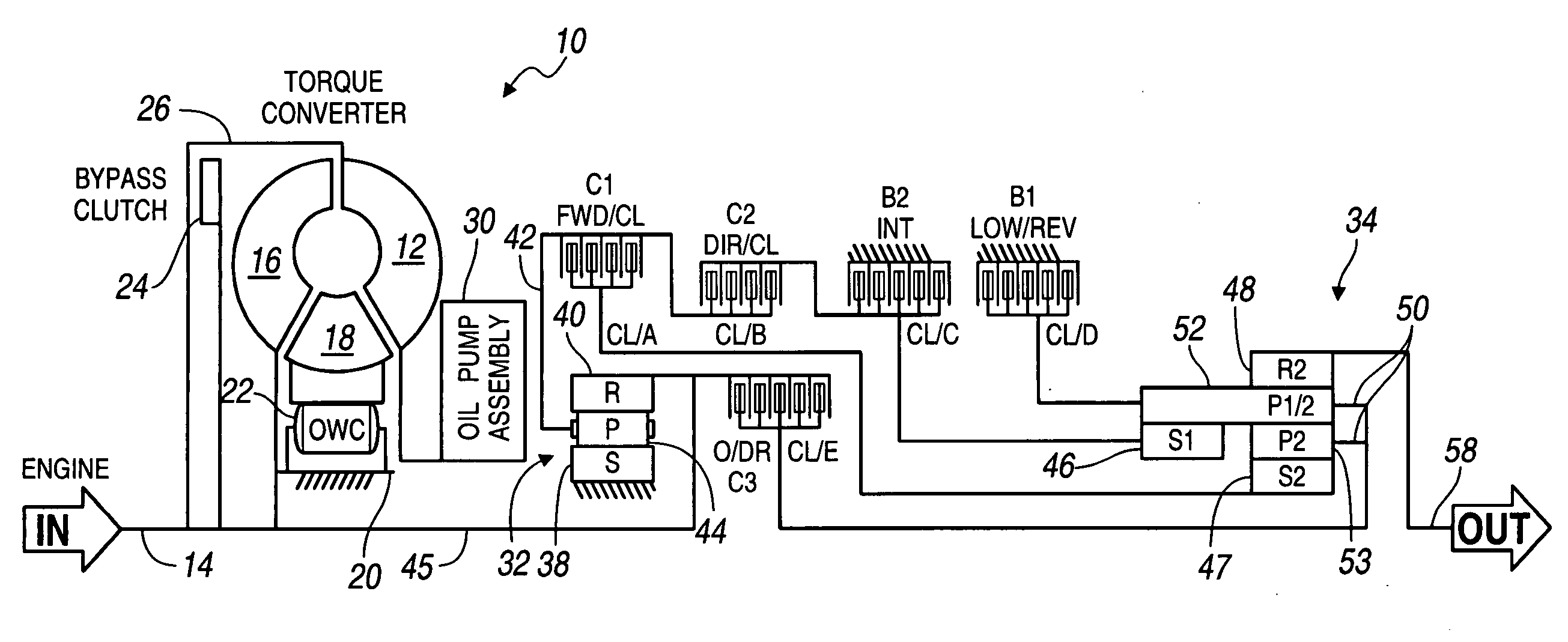
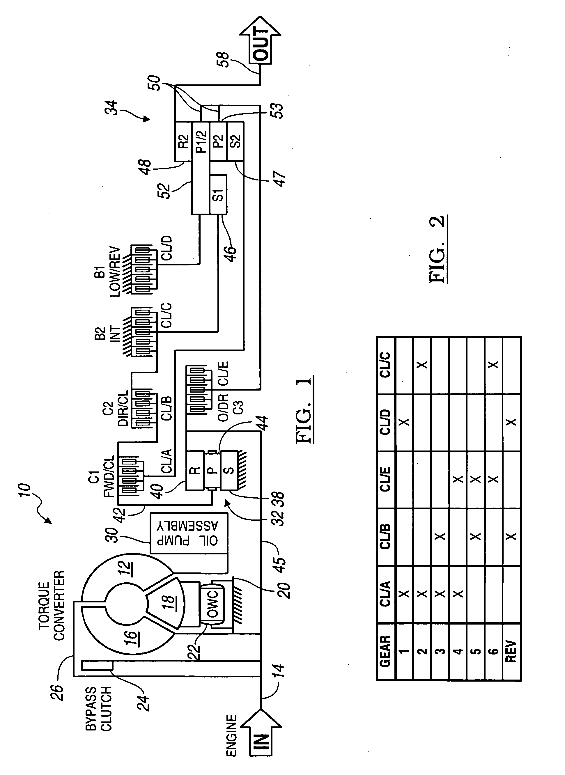
[0034]Referring now to the drawings, there is illustrated in FIG. 1 the kinematic arrangement of an automatic transmission. The torque converter 10 includes an impeller wheel 12 connected to the crankshaft 14 of an internal combustion engine, a bladed turbine wheel 16, and a bladed stator wheel 18. The impeller, stator and turbine wheels define a toroidal fluid flow circuit, whereby the impeller is hydrokinetically connected to the turbine. The stator 18 is supported rotatably on a stationary stator sleeve shaft 20, and an overrunning brake 22 anchors the stator to the shaft 20 to prevent rotation of the stator in a direction opposite the direction of rotation of the impeller, although free-wheeling motion in the opposite direction is permitted.

[0035]The torque converter assembly includes a lockup or bypass clutch 24 located within the torque converter impeller housing 25. When clutch 24 is engaged, the turbine and impeller are mechanically connected; when clutch 24 is disengaged, t...


PUM


Abstract

A method for executing a downshift in a transmission includes starting disengagement of a second control element after starting disengagement of a first element. Disengagement of the second element starts before starting engagement of a fourth element. A third element is forced to synchronous speed by beginning engagement of the fourth element before engaging the third element. Engagement of the third and fourth elements is completed at the end of the downshift.

Description


Claims


Application Information

Patent Timeline
Owner FORD GLOBAL TECH LLC
Why Eureka
Try Eureka