Reinforcing bar joint

a technology of reinforcement bar and joint, applied in the direction of building reinforcement, construction, building components, etc., can solve the problems of increasing bar diameter, insufficient versatility in terms of bar pitch, and difficulty in performing various bar arrangements or ensuring overlapping lengths, etc., to achieve the effect of strengthening the joining for

Inactive Publication Date: 2010-04-15
OKABE CO LTD
View PDF8 Cites 10 Cited by
  • Summary
  • Abstract
  • Description
  • Claims
  • Application Information

AI Technical Summary

Benefits of technology

[0017]The present invention has been developed in view of the foregoing circumstances, and it is thus an object thereof to provide a reinforcing bar joint which is capable of avoiding the rotation of its sleeve, providing an enhanced joining force between reinforcing bars.
[0018]Another object of the present invention is to provide a reinforcing bar joint which is capable of suppressing bending of the reinforcing bars at the position where a wedge member is driven in.
[0022]In addition to this, since the two reinforcing bars are arranged in series along an identical line, tensile loads from the respective reinforcing bars act on the sleeve along the same line of action. This eliminates the possibility of rotating the sleeve as heretofore discussed.

Problems solved by technology

Since two reinforcing bars must be overlapped, it becomes harder to perform various bar arrangements or secure overlapping lengths of such as the bar diameter increases.
Nevertheless, among those methods, one method for joining pairs of mutually parallel reinforcing bars is applicable only to reinforcing bars having fixed spacings, and thus is not sufficiently versatile in terms of bar pitch (see patent document 1).
Moreover, joining methods that use a U-shaped sleeve cannot provide sufficient joint strength (see patent documents 2 and 3).
This precludes the two reinforcing bars from being joined along an identical line, and a problem exists in that it is difficult to provide sufficient clearances between reinforcing bars when a large number of reinforcing bars are required due to seismic standards or the like.
There has also been the problem that if a tensile force acts on the two reinforcing bars, the sleeve can be rotated due to the foregoing gap in the direction that is orthogonal to the axes, thereby loosening the engagement between the reinforcing bars and the wedge member.
There has thus been a problem that it is difficult to form the bar arrangement as intended, resulting in interference or insufficient spacing between the reinforcing bars.

Method used


Image

  • Reinforcing bar joint
  • Reinforcing bar joint
  • Reinforcing bar joint

Examples


first embodiment

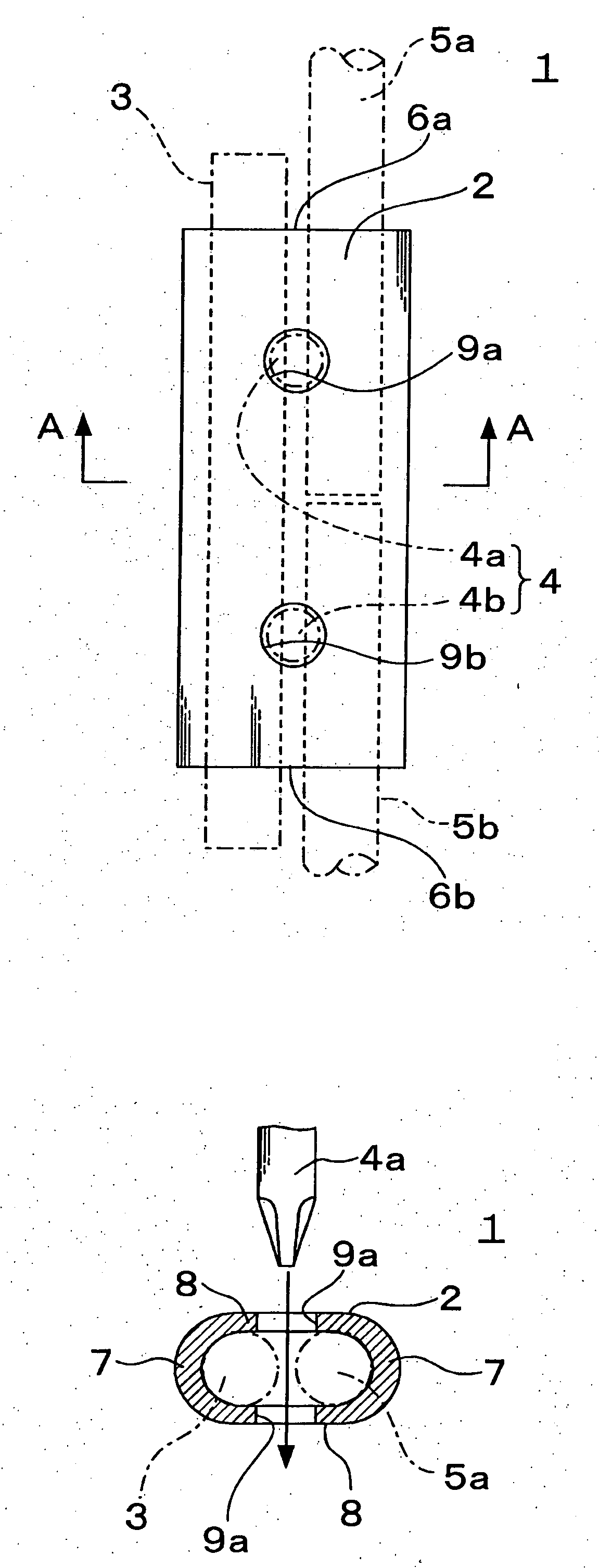
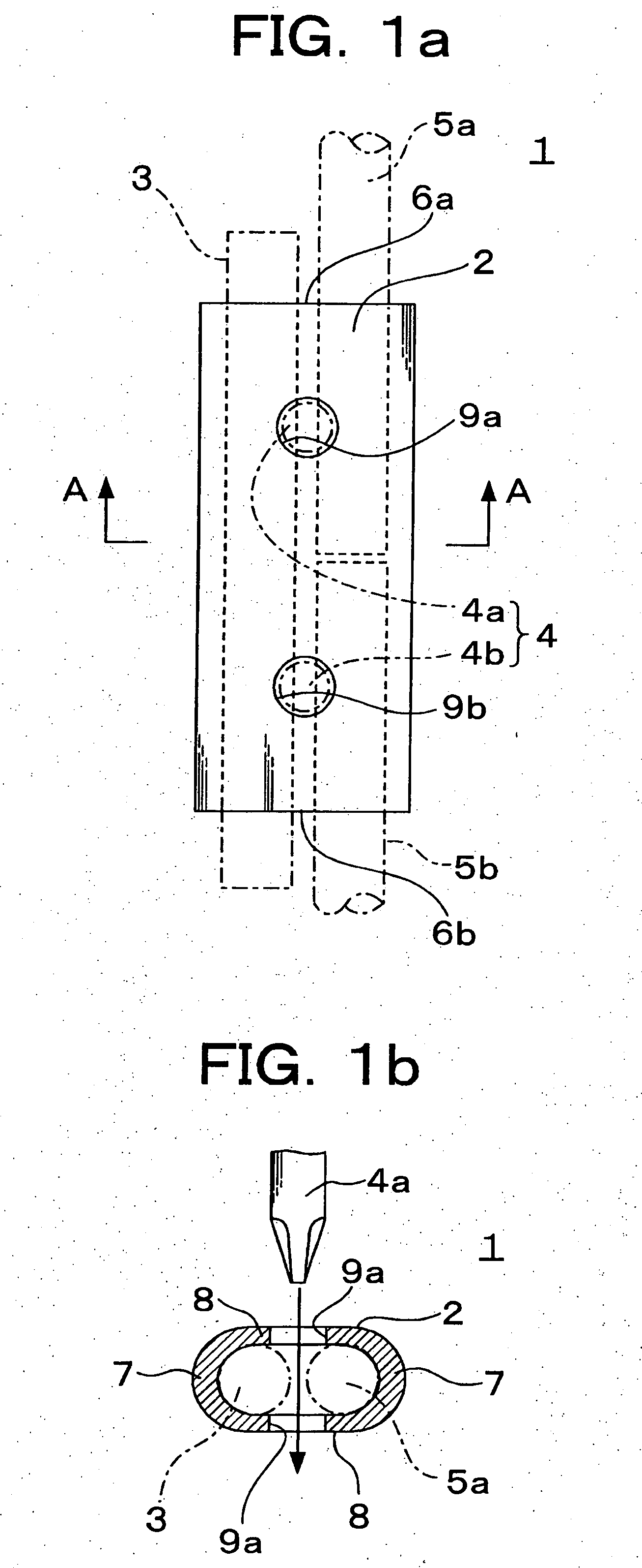
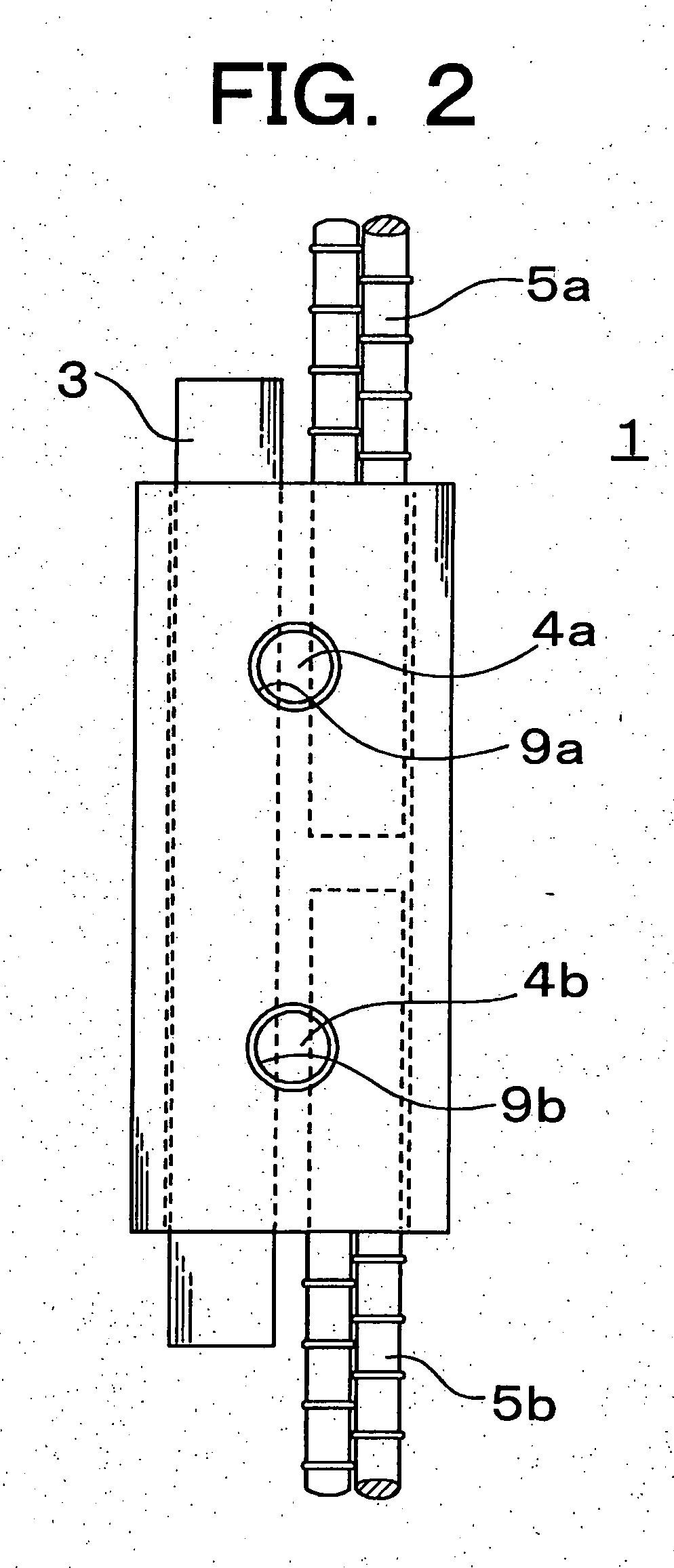
[0054]FIG. 1 is a diagram showing a reinforcing bar joint according to the present embodiment. As shown in the diagram, the reinforcing bar joint 1 according to the present embodiment comprises an elliptic-sectioned sleeve 2, a load transfer rod 3 to be inserted through the sleeve, and wedging means 4.

[0055]The sleeve 2 is configured so that end portions of reinforcing bars 5a, 5b can be inserted into openings 6a, 6b formed in both ends of the sleeve 2 so that the reinforcing bars are arranged in series along an identical line. The load transfer rod 3 can also be inserted therethrough in parallel with the end portions of the reinforcing bars 5a, 5b which are inserted into the sleeve 2.

[0056]The sleeve 2 is composed of a pair of semicylindrical wall portions 7, 7 which are arranged with their curved inner surfaces opposing each other, and a pair of flat wall portions 8, 8 which extend to the corresponding edges of the pair of semicylindrical wall portions. Wedge insertion holes 9a, 9...

embodiment 1

[0074]The following tensile tests were undertaken in order to examine what effects the relative difference in hardness between the reinforcing bars and the load transfer rod has on the tensile characteristics of the reinforcing bar joint according to the present invention.

[0075]The tensile tests undertaken used wedge members having a wedge length of 48 mm, a wedge diameter of 16 mm, and a tip length of 10 mm. Table 1 shows specifications of the sleeves.

TABLE 1thicknesswedgeofinsertionCASESteelLWW1HH1sleeveholeNo.type(mm)(mm)(mm)(mm)(mm)(mm)(mm)1~5STKM 13A140342256.544.56.016.56 7   8 9S45C S45C (annealed) S45C S45C (annealed)220 220   230 23034.4 34.3 34.3 40.0 39.3 40.724.9 24.6 24.6 28.0 28.5 29.862.7 63.1 63.0 69.4 69.9 69.653.3 53.2 53.5 58.1 58.6 58.04.7 4.9 4.8 5.8 5.5 5.616.5

[0076]As can be seen from Table 1, the sleeves tested were of three steel types: STKM13A (carbon steel for machine structural use, JIS), S45C (non-heat treated), and S45C (annealed). The wedge members wer...

second embodiment

[0092]A description will now be given of a second embodiment. It should be appreciated that components and the like substantially identical to those of the foregoing embodiment will be designated by the same reference numerals, and a description thereof will be omitted here.

[0093]FIG. 3 is a diagram showing a reinforcing bar joint according to the second embodiment. As shown in the diagram, the reinforcing bar joint 41 according to the present embodiment comprises an elliptic-sectioned sleeve 2, a load transfer rod 43 to be inserted through the sleeve, and wedging means 4.

[0094]The load transfer rod 43 is composed of a rod body 45 and large diameter portions 44a, 44b which are protruding portions to be attached to respective ends of the rod body. The large diameter portions 44a, 44b are formed to have an outer diameter that is greater than the rod body 45, and internal threads are cut in their internal cavities.

[0095]Conversely, the rod body 45 is made of a straight steel rod having...


PUM


Abstract

To avoid the rotation of a sleeve, providing an enhanced joint force. A reinforcing bar joint 1 according to the present invention includes an elliptic-sectioned sleeve 2, a load transfer rod 3 to be inserted through the sleeve, and wedging means 4. The sleeve 2 is configured so that end portions of reinforcing bars 5a, 5b can be inserted into openings 6a, 6b formed in respective ends of the sleeve 2 so that the reinforcing bars are arranged in series along an identical line. The load transfer rod 3 can also be inserted therethrough in parallel with the end portions of the reinforcing bars 5a, 5b which are inserted into the sleeve 2.

Description

TECHNICAL FIELD[0001]The present invention relates to a reinforcing bar joint to be used for joining reinforcing bars.BACKGROUND ART[0002]Reinforcing bars are main components of reinforced concrete structures (RC structures) and steel-reinforced concrete structures (SRC structures), and are cut in predetermined lengths so as to be arranged easily during configuration on-site. The operation of joining reinforcing bars on-site is thus indispensable.[0003]There are various types of methods for joining reinforcing bars, including a lap joint, a mechanical coupler, and a gas-pressure welding joint. These joints are selected and used as appropriate depending on the quality required of a structure, working conditions, the diameters of the reinforcing bars being used, and the like.[0004]In this instance, the joining methods mentioned above have respective drawbacks and advantages. For example, a lap joint can join reinforcing bars easily by utilizing the bar's adhesion to concrete. Since tw...

Claims


Application Information

Patent Timeline
Patent Type & Authority Applications(United States)
IPC IPC(8): E04B1/58E04C5/16E04C5/12
CPCE04C5/165
Inventor MURAYAMA, SATOSHIYOSHIDA, MITSUHIROHIRAYAMA, TAKAAKIKURIHARA, YOSHITAKACRAMER, ANDREW R.
Owner OKABE CO LTD
Why Eureka
Try Eureka