Combustion liner damper

a technology of combustion liner and damper, which is applied in the direction of shock absorbers, machines/engines, lighting and heating apparatus, etc., can solve the problems of excessive vibration and wear of the interface between these two components of the combustion system, and achieve the effects of reducing vibration, dampening vibration, and reducing radial heigh

Active Publication Date: 2010-04-15
ANSALDO ENERGIA SWITZERLAND AG
View PDF10 Cites 19 Cited by
  • Summary
  • Abstract
  • Description
  • Claims
  • Application Information

AI Technical Summary

Benefits of technology

[0006]Embodiments of the present invention are directed towards a system and method for, among other things, providing a way of reducing the vibrations and relative motion between mating components of a gas turbine combustor. The present invention provides an embodiment directed towards a gas turbine combustor comprising a flow sleeve having a plurality of liner stops and a combustion liner located radially within the flow sleeve. One or more spring dampers are positioned between the combustion liner and the flow sleeve. The spring dampers are configured so as to permit compression. This compression occurs primarily as the combustion liner moves radially outward towards the flow sleeve during operation at elevated temperatures. The spring damper maintains contact with both the flow sleeve and the combustion liner so as to dampen the vibrations between the mating components.
[0008]The present invention also comprises a method of reducing vibrations between a combustion liner and a flow sleeve in a gas turbine combustor. A combustion liner is inserted radially within a flow sleeve and once located in the desired axial position, one or more spring dampers are compressed, so as to reduce their radial height. The one or more spring dampers are compressed by pressing portions of the inner radial wall and the outer radial wall towards each other. The compressed spring dampers are placed radially between the combustion liner and the flow sleeve and then released from the compressed state. As a result, the spring damper applies a pressure load to the combustion liner and the flow sleeve which serves to dampen vibrations that occur between the combustion liner and flow sleeve.

Problems solved by technology

However, the interface between these two components of the combustion system can give rise to excessive vibrations and wear due to gaps that exist in the assembly between the combustion liner to the flow sleeve.

Method used


Image

  • Combustion liner damper
  • Combustion liner damper
  • Combustion liner damper

Examples


Embodiment Construction

[0019]The subject matter of the present invention is described with specificity herein to meet statutory requirements. However, the description itself is not intended to limit the scope of this patent. Rather, the inventors have contemplated that the claimed subject matter might also be embodied in other ways, to include different components, combinations of components, steps, or combinations of steps similar to the ones described in this document, in conjunction with other present or future technologies.

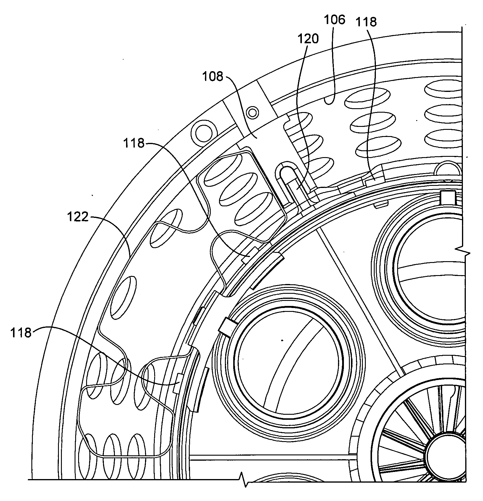
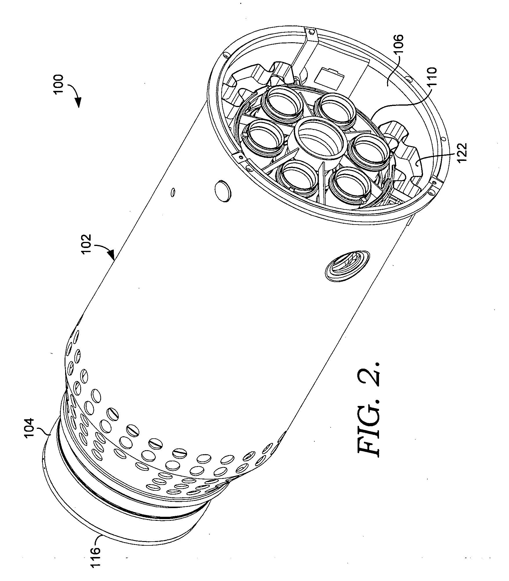
[0020]The present invention will now be described with reference to the accompanying FIGS. 2-8. Referring initially to FIGS. 2 and 3, a gas turbine combustor 100 is shown having a flow sleeve 102 and a combustion liner 104. The flow sleeve 102 has a sleeve wall 106 with a first diameter D1, and a plurality of liner stops 108 that extend radially inward from the sleeve wall 106.

[0021]The combustion liner 104 comprises a generally annular liner wall 110 having a second diameter D2 tha...


PUM


Abstract

The present invention are directed towards a system and method for providing a way of reducing the vibrations and wear between mating components of a gas turbine combustor. The gas turbine combustor includes a flow sleeve having a plurality of liner stops and a combustion liner located radially within the flow sleeve. Spring dampers are positioned between the combustion liner and the flow sleeve to restrict the relative movement between the flow sleeve and the combustion liner and dampen vibrations at their assembly location. The spring dampers are capable of compressing to permit thermal growth between the combustion liner and flow sleeve.

Description

CROSS-REFERENCE TO RELATED APPLICATIONS[0001]Not applicable.TECHNICAL FIELD[0002]The present invention relates to gas turbine engines. More particularly, embodiments of the present invention relate to an apparatus and method for damping vibrations that occur in a gas turbine combustor.BACKGROUND OF THE INVENTION[0003]Gas turbine engines operate to produce mechanical work or thrust. One type of gas turbine engine is a land-based engine that has a generator coupled thereto which harnesses the mechanical work for the purposes of generating electricity. A gas turbine engine typically comprises at least a compressor section having a series of rotating compressor blades, one or more combustors, and a turbine section. Air enters the engine through an inlet and then passes through the compressor, where the rotating blades compress the air and raise its pressure.[0004]The compressed air flows from the compressor and towards the combustion section. For an individual combustor, a flow sleeve e...

Claims


Application Information

Patent Timeline
Patent Type & Authority Applications(United States)
IPC IPC(8): F23R3/60F02C7/20F16F7/00
CPCF23R3/60F16F1/025
Inventor ELLIS, CHARLIECALDERON, CARLOS
Owner ANSALDO ENERGIA SWITZERLAND AG
Why Eureka
Try Eureka