Hybrid heating system and method

a heating system and hybrid technology, applied in the field of hybrid heating systems and methods, can solve the problems of reducing the amount of extracted heat, affecting and affecting the efficiency of the heat pump, so as to maximize the economic benefits of the heat pump

Inactive Publication Date: 2010-04-15
NAGHSHINEH REZA
View PDF13 Cites 28 Cited by
  • Summary
  • Abstract
  • Description
  • Claims
  • Application Information

AI Technical Summary

Benefits of technology

[0005]The present invention overcomes the above-identified and other problems and disadvantages by providing a hybrid heating system and method in which an indoor coil of a heat pump is located upstream of the heat output of a non-electric second heat source, e.g., a gas or liquefied petroleum gas furnace; the heat pump continues to operate even at very low temperatures, i.e., below 0° F.; and the second heat source supplements the heat output of the heat pump as needed to maintain a desired indoor temperature, thereby maximizing economic benefit from the heat pump.

Problems solved by technology

However, as the temperature of the outdoor air decreases, the amount of extracted heat also decreases until a desired temperature within the enclosed space can no longer be maintained by operation of the heat pump alone.
The main reason that the heat pump is turned off is that its indoor coil is located downstream of the furnace, such that the heat pump's compressor would experience a damagingly high compression ratio due to the furnace-heated air flowing through the indoor coil.
Unfortunately, it is both time-consuming and expensive to reconfigure a building from gas to total electric heat.
Reconfiguring a building from gas to total electric heat requires replacing the smaller ductwork, much of which may be very difficult to access, with larger ductwork to accommodate a larger volume of air.

Method used


Image

  • Hybrid heating system and method
  • Hybrid heating system and method
  • Hybrid heating system and method

Examples


Embodiment Construction

.

BRIEF DESCRIPTION OF THE DRAWING FIGURES

[0009]The present invention is described herein with reference to the following drawing figures, which are not necessarily to scale:

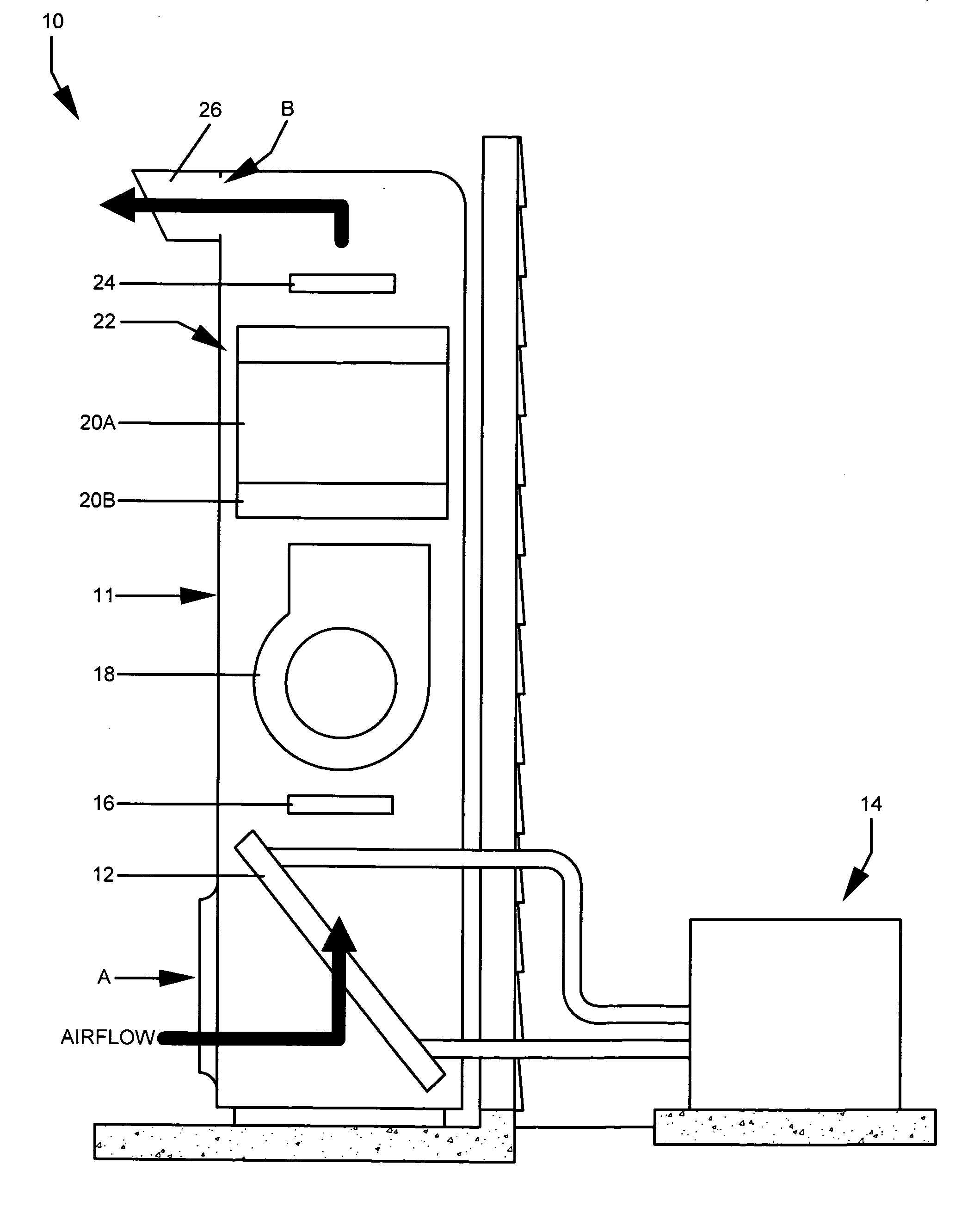
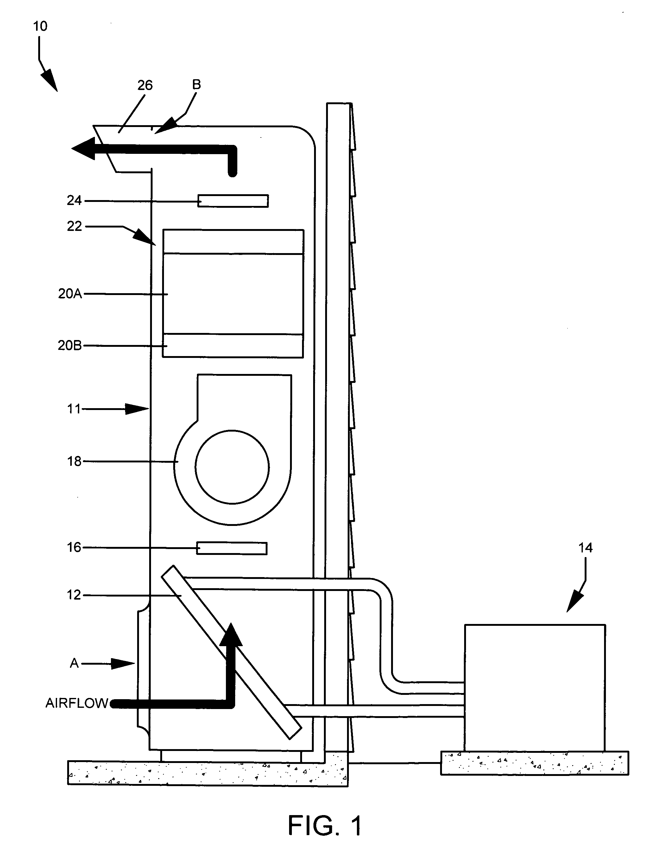
[0010]FIG. 1 is a cross-sectional elevation view representation of an embodiment of the system of the present invention; and

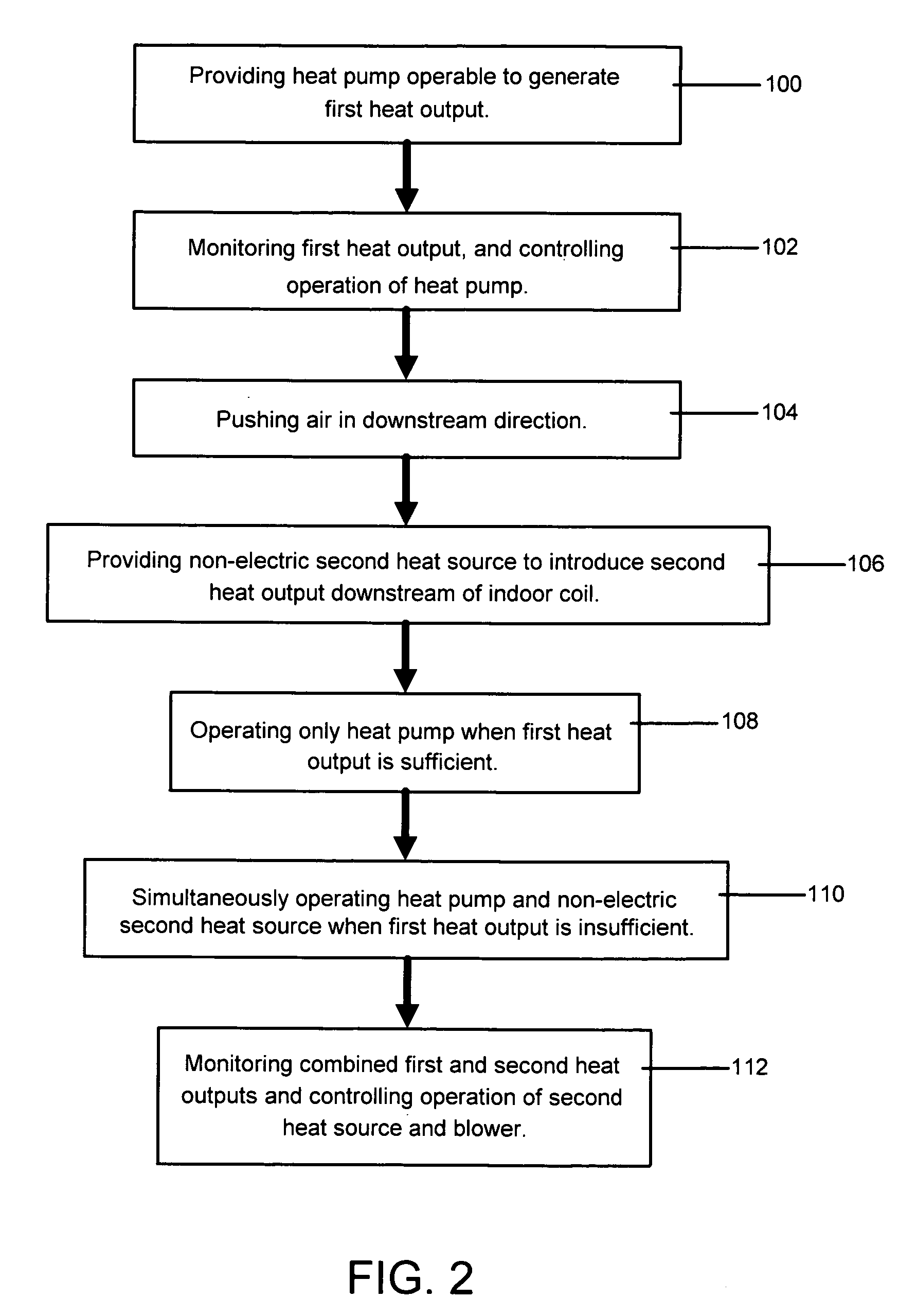
[0011]FIG. 2 is a flowchart setting forth steps of an embodiment of the method of the present invention.

DETAILED DESCRIPTION OF THE INVENTION

[0012]With reference to the drawing figures, a system and method is herein described, shown, and otherwise disclosed in accordance with various embodiments, including a preferred embodiment, of the present invention.

[0013]Broadly, the present invention concerns a hybrid heating system 10 and method for reaching and maintaining a desired temperature in an enclosed space, in which an indoor coil of a heat pump is located upstream of the heat output of a non-electric second heat source, e.g., a gas or liquefied petroleum gas furnace; the heat pump continue...


PUM


Abstract

A hybrid heating system (10) and method in which an indoor coil (12) of a heat pump (14) is located upstream of a heat output of a non-electric second heat source (22), e.g., a gas or liquefied petroleum gas furnace. The heat pump (14) continues to operate even at low temperatures, i.e., below 0° F., and the non-electric second heat source (22) supplements the heat output of the heat pump (12) as needed to maintain a desired indoor temperature, thereby maximizing economic benefit from the heat pump (12).

Description

FIELD OF THE INVENTION[0001]The present invention relates to hybrid heating systems and methods. More specifically, the present invention concerns a hybrid heating system and method in which an indoor coil of a heat pump is located upstream of the heat output of a non-electric second heat source, e.g., a gas or liquefied petroleum gas furnace; the heat pump continues to operate even at low temperatures, i.e., below 0° F.; and the second heat source supplements the heat output of the heat pump as needed to maintain a desired indoor temperature, thereby maximizing economic benefit from the heat pump.BACKGROUND OF THE INVENTION[0002]Heat pumps operate by extracting heat from outdoor air, and transferring that heat to an enclosed space, such as a home or business. Heat pumps are generally more economical to operate than conventional furnaces that burn fossil fuels. However, as the temperature of the outdoor air decreases, the amount of extracted heat also decreases until a desired tempe...

Claims


Application Information

Patent Timeline
Patent Type & Authority Applications(United States)
IPC IPC(8): F24D15/04
CPCF24D2200/04F24D2200/12F24H9/2085F24H9/2071F24H3/12F24H15/208F24H15/136F24H15/36F24H15/345F24H15/375
Inventor NAGHSHINEH, REZA
Owner NAGHSHINEH REZA
Why Eureka
Try Eureka