
Method of and apparatus for measuring electric field vector and microscope using same

a technology of electric field vector and microscope, which is applied in the direction of optical radiation measurement, instruments, measurement devices, etc., can solve the problems of not being able to measure the optical properties of objects or specimens, the optical resolution of the near-field optical microscope is limited not by a diffraction limit, but by the size of the probe, etc., to achieve more interpretable and improve the effect of precision

Inactive Publication Date: 2010-04-15
SAMSUNG ELECTRONICS CO LTD +1
View PDF4 Cites 2 Cited by
  • Summary
  • Abstract
  • Description
  • Claims
  • Application Information

AI Technical Summary

Benefits of technology

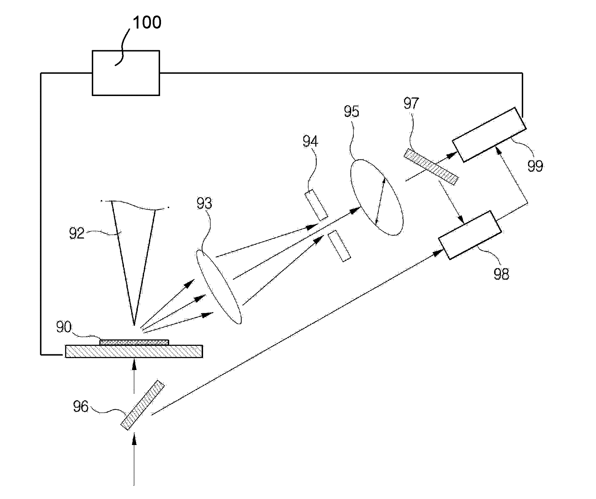
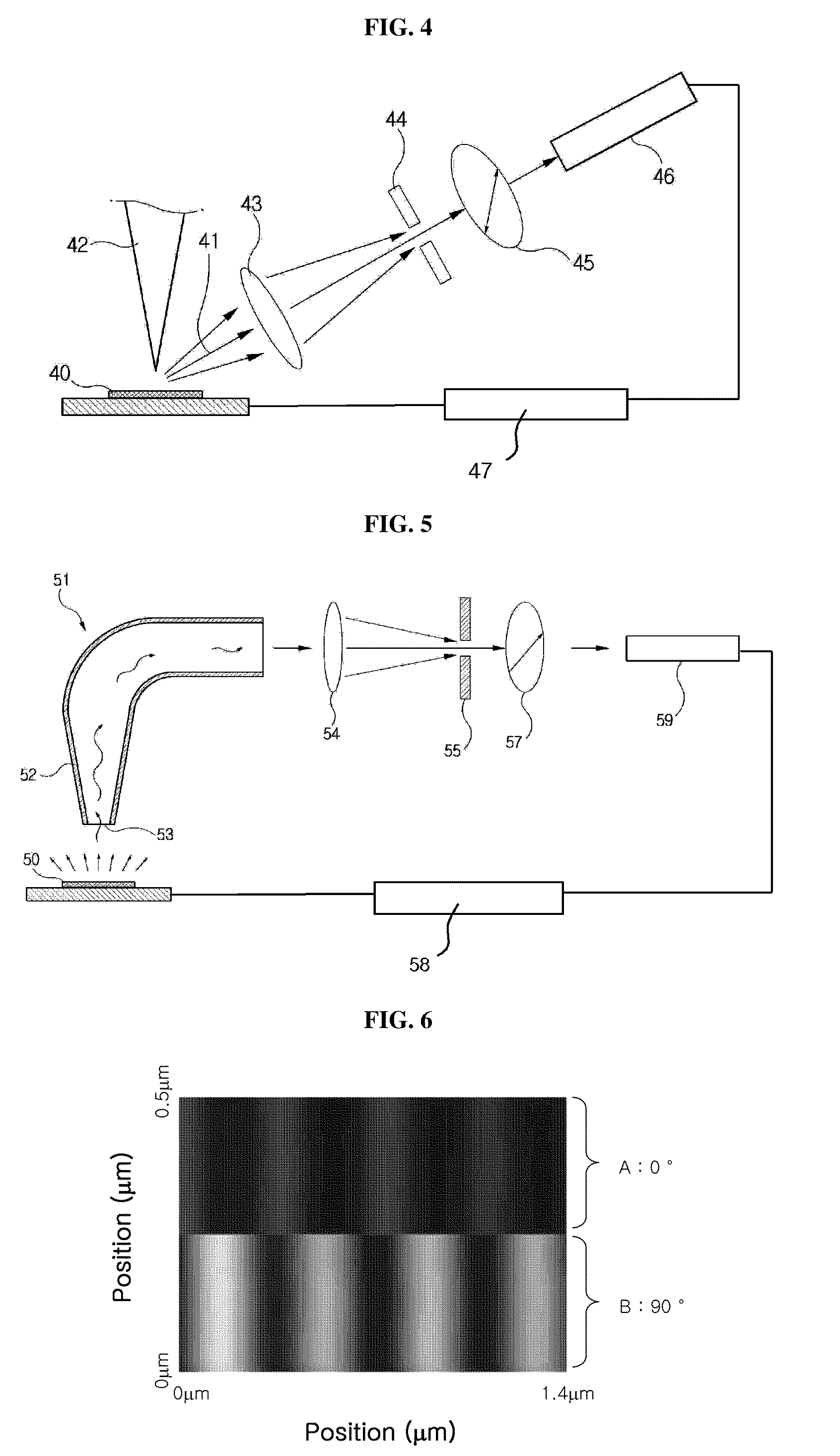
[0036]Thus, according to exemplary embodiments of the present invention, characteristics of an electric field vector (e.g., size, orientation axis and/or orientation) are measured with a resolution of nanometers. In addition, using the measurement results, a distribution of electric field vectors in an examination area are mapped into a two- or three-dimensional form. Therefore, optical phenomena occurring in a structure having a size less than a few hundred nanometers, such as nano-particle

Problems solved by technology

However, neither the scanning electron microscope nor the atomic force microscope are capable of measuring optical properties of an object or specimen.
The near-field optical microscope does not, however, measure interaction between atoms.
Accordingly, an optical resolution of the near-field optical microscope is limited not by a diffraction limit, but by a size of the probe.
Thus, the apertureless scanning optical microscope provides high resolution power which is unattainable with an apertured near-field scanning optical microscope.
Thus, existing techniques can not measure an orientation of the electric field formed around the specimen and, more so, cannot measure the orientation of the electric field on the order of nanometers.

Method used


Image

  • Method of and apparatus for measuring electric field vector and microscope using same
  • Method of and apparatus for measuring electric field vector and microscope using same
  • Method of and apparatus for measuring electric field vector and microscope using same

Examples


Embodiment Construction

[0049]The invention will now be described more fully hereinafter with reference to the accompanying drawings, in which exemplary embodiments of the invention are shown. The present invention may, however, be embodied in many different forms and should not be construed as limited to the embodiments set forth herein. Rather, these embodiments are provided so that this disclosure will be thorough and complete, and will fully convey the scope of the invention to those skilled in the art. Like reference numerals refer to like elements throughout.

[0050]It will be understood that when an element is referred to as being “on” another element, it can be directly on the other element or intervening elements may be present therebetween. In contrast, when an element is referred to as being “directly on” another element, there are no intervening elements present. As used herein, the term “and / or” includes any and all combinations of one or more of the associated listed items.

[0051]It will be unde...


PUM


Abstract

A system for measuring an electric field vector includes an optical extractor configured to extract an optical signal having a spatial resolution of a nanometer level. The optical signal corresponds to incident light at a measuring position within an examination area of a surface of a specimen. The system further includes a polarization analyzer for analyzing a polarization characteristic of the optical signal extracted by the optical extractor, and an electric field vector determinator for determining at least a size and an orientation axis of an electric vector at the measuring position using the polarization characteristic analyzed by the polarization analyzer.

Description

CROSS-REFERENCE TO RELATED APPLICATIONS[0001]This application claims priority to Patent Cooperation Treaty Application No. PCT / KR2007 / 001432, filed on Mar. 23, 2007, and Korean Patent Application No. 10-2008-0130091, filed Dec. 19, 2006, and all the benefits accruing therefrom under 35 U.S.C. §§119 and 365, the contents of which in their entireties are herein incorporated by referenceBACKGROUND[0002]1) Field[0003]The following description relates generally to measurement of an electric field vector, and, more specifically, to a method of and a system for measuring an electric field vector having a nanometer-level resolution, and to a microscope using the method and / or the system.[0004]2) Description of the Related Art[0005]When observing an object, either with a naked eye or with the aid of a microscope, for example, when a size of the object is less than half of a wavelength of measuring light, an image of the object cannot be seen due to a diffraction limit. Thus, scanning electro...

Claims


Application Information

Patent Timeline
IPC IPC(8): G01J4/00G01B9/02
CPCB82Y20/00G01Q60/22B82Y35/00G01B21/00
Inventor KIM, DAI SIKLEE, KWANG GEOLKIHM, HYUN WOO
Owner SAMSUNG ELECTRONICS CO LTD
Learn More