
Optical apparatus

Active Publication Date: 2010-04-15
OM DIGITAL SOLUTIONS CORP
View PDF6 Cites 10 Cited by
  • Summary
  • Abstract
  • Description
  • Claims
  • Application Information

AI Technical Summary

Benefits of technology

[0017]With the present invention as described above, it is possible to achieve an optical apparatus allowing images in multiple directions to be simultaneously taken with simple construction using a prism optical system yet with high definitions even at wide angles of view.

Problems solved by technology

With the conventional imaging apparatus capable of taking images in both the right and left directions with a prism provided in front of the imaging lens, however, the angles of view in the right and left directions become inevitably narrow because the angle of view of the imaging lens is divided into two equal parts: one for taking images in the left direction and another for taking images in the right direction.
The resolving power depends on the imaging lens; trying to increase the resolving power around the angle of view unavoidably makes the imaging lens structurally complicated.

Method used


Image

  • Optical apparatus
  • Optical apparatus
  • Optical apparatus

Examples


example 1

[0096]

SurfaceRadius ofSurfaceDisplacementRefractiveAbbe'sNo.curvatureseparationand tiltindexNo.Object∞∞plane 1 9.581.001.487570.4 2ASS [1]3.00 3ASS [2]2.001.846723.8 415.331.00 5∞ (Stop) 6FFS [1](1)1.806140.9 7FFS [2] (RS)(2)1.806140.9 8FFS [3] (RS)(3)1.806140.9 9FFS [2](2)10∞1.00(4)1.516364.111∞0.10Image∞planeASS [1]R2.66k−2.0725 × 10⁻²  b7.2049 × 10−5ASS [2]R5.37k2.7549b1.0193 × 10−5FFS [1]C49.1284 × 10−3C6−6.2245 × 10⁻²FFS [2]C42.2356 × 10−2C6−8.2677 × 10⁻³C8−4.3925 × 10⁻⁴C10−4.9405 × 10⁻⁵  FFS [3]C43.1574 × 10−2C6  1.1019 × 10⁻²C8  1.7708 × 10⁻⁴C10−5.9253 × 10⁻⁴  Displacement and tilt (1)X0.00Y0.00Z0.10α4.75β0.00γ0.00Displacement and tilt (2)X0.00Y0.00Z5.91α−48.61β0.00γ0.00Displacement and tilt (3)X0.00Y6.08Z7.06α−71.52β0.00γ0.00Displacement and tilt (4)X0.00Y0.00Z13.20α135.00β0.00γ0.00

example 2

[0097]

SurfaceRadius ofSurfaceDisplacementRefractiveAbbe'sNo.curvatureseparationand tiltindexNo.Object∞∞plane1∞ (Stop)2FFS [1](1)1.806140.93FFS [2] (RS)(2)1.806140.94FFS [3] (RS)(3)1.806140.95FFS [2](2)68.362.00(4)1.487570.476.501.008∞1.001.516364.19∞0.10Image∞planeFFS [1]C41.3373 × 10−2C61.3725 × 10−2FFS [2]C45.7393 × 10−3C65.4512 × 10−3C8−1.9425 × 10⁻⁵C10−5.2533 × 10⁻⁴  C113.1447 × 10−4C13  6.3886 × 10⁻⁵C155.6041 × 10−5FFS [3]C42.0000 × 10−2C62.0000 × 10−2C8  3.3583 × 10⁻⁴C108.4202 × 10−6C116.6984 × 10−5C13−4.6499 × 10⁻⁵C15−2.2973 × 10⁻⁶  Displacement and tilt (1)X0.00Y0.00Z0.50α7.76β0.00γ0.00Displacement and tilt (2)X0.00Y0.00Z3.98α−46.18β0.00γ0.00Displacement and tilt (3)X0.00Y5.79Z4.82α−75.44β0.00γ0.00Displacement and tilt (4)X0.00Y0.00Z8.56α120.00β0.00γ0.00

example 3

[0098]

SurfaceRadius ofSurfaceDisplacementRefractiveAbbe'sNo.curvatureseparationand tiltindexNo.Object∞∞plane1∞ (Stop)2FFS [1](1)1.806140.93FFS [2] (RS)(2)1.806140.94FFS [3] (RS)(3)1.806140.95FFS [2](2)6∞1.00(4)1.516364.17∞0.10Image∞planeFFS [1]C41.8025 × 10−2C62.4696 × 10−2FFS [2]C47.7096 × 10−3C66.6093 × 10−3C8−6.5307 × 10⁻⁴C10−7.0855 × 10⁻⁴  C112.5191 × 10−4C13−1.6152 × 10⁻⁶C157.0169 × 10−5FFS [3]C42.0000 × 10−2C62.0000 × 10−2C8−8.7665 × 10⁻⁵C103.4103 × 10−6C116.1612 × 10−5C13  6.8121 × 10⁻⁶C152.9135 × 10−5Displacement and tilt (1)X0.00Y0.00Z0.50α2.70β0.00γ0.00Displacement and tilt (2)X0.00Y0.00Z4.30α−49.35β0.00γ0.00Displacement and tilt (3)X0.00Y8.01Z5.81α−78.40β0.00γ0.00Displacement and tilt (4)X0.00Y0.00Z10.78α120.00β0.00γ0.00

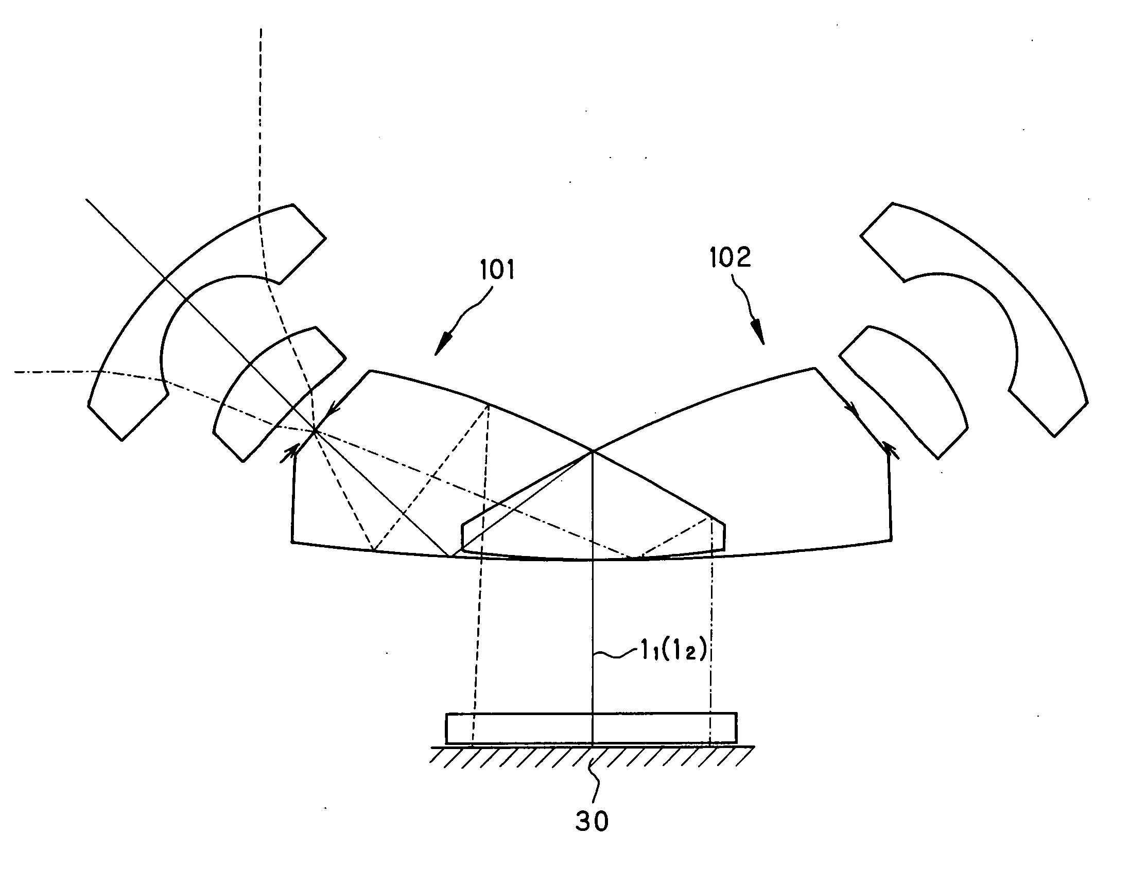
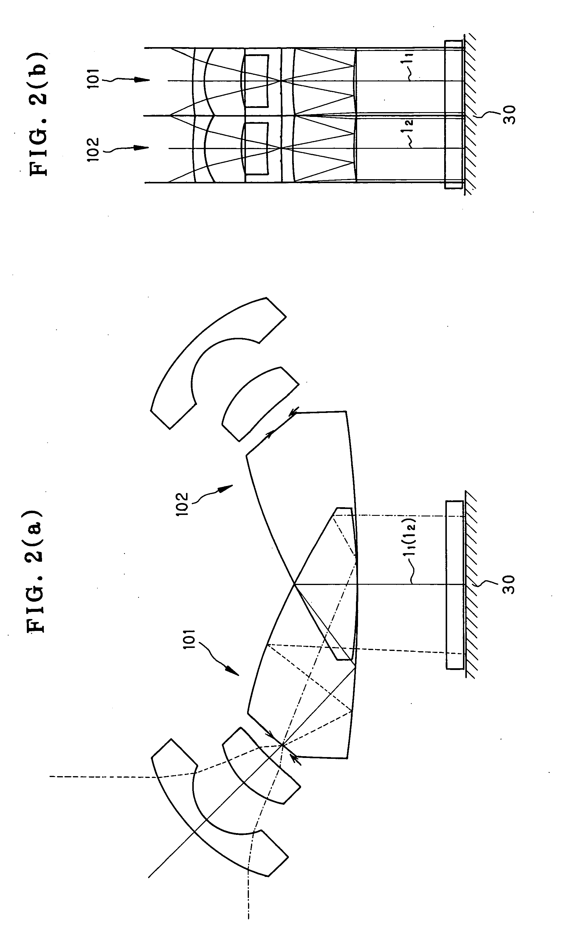
[0099]As shown in FIG. 11, the inventive optical apparatus 100 capable of simultaneously taking images in both the right and left directions may typically be used as a double-side monitor of the front of a car V to be attached to the end of the car.

[0100]T...


PUM


Abstract

The invention relates to an optical apparatus allowing images in multiple directions to be simultaneously taken with simple construction using a prism optical system yet with high definitions even at wide angles of view. Specifically, the invention provides an optical apparatus using a prism optical system which has three optical surfaces: a first surface having transmission, a second surface having internal reflection plus transmission and a third surface having reflection and is formed of a medium having a refractive index of 1.3 or greater and in which light enters the medium through the first surface, is totally reflected at the second surface, and then reflected at the third surface 13, and finally leaves the medium this time through the second surface. At least two prism optical systems (101, 102) are arranged side by side with respect to an imaging plane of a single imaging device (30) so that images in at least two directions are formed side by side on the imaging plane of the single imaging device (30), and at least one of three surfaces of each of said prism optical systems (101, 102) has a reflecting surface defined by a rotationally asymmetric plane.

Description

TECHNICAL FIELD[0001]The present invention relates generally to an optical apparatus, and more particularly to an optical apparatus capable of simultaneously taking images in different directions with a single imaging device.BACKGROUND ART[0002]Among already known on-vehicle cameras capable of simultaneously viewing both the right and left directions, there is an imaging apparatus wherein images in both the right and left directions are arranged and taken on the same imaging plane with one or two prisms provided in front of an imaging lens (see Patent Publications 1 and 2).[0003]Among already known small-format imaging optical systems capable of producing less distorted images at wide angles of view, on the other hand, there is a prism optical system that, as set forth in Patent Publication 3 or the like, comprises a first surface having transmission, a second surface having reflection plus transmission and a third surface having reflection, wherein at least the surface having refle...

Claims


Application Information

Patent Timeline
IPC IPC(8): G02B5/04
CPCB60R3/005B60R11/04B60R2011/004G03B15/00G02B13/06G02B13/22G02B17/0856G02B5/04
Inventor TOGINO, TAKAYOSHI
Owner OM DIGITAL SOLUTIONS CORP
Features
  • Generate Ideas
  • Intellectual Property
  • Life Sciences
  • Materials
  • Tech Scout
  • Unparalleled Data Quality
  • Higher Quality Content
  • 60% Fewer Hallucinations
Learn More