
Channel allocation method and apparatus for wireless communication networks

Inactive Publication Date: 2010-04-15
SAMSUNG ELECTRONICS CO LTD
View PDF6 Cites 38 Cited by
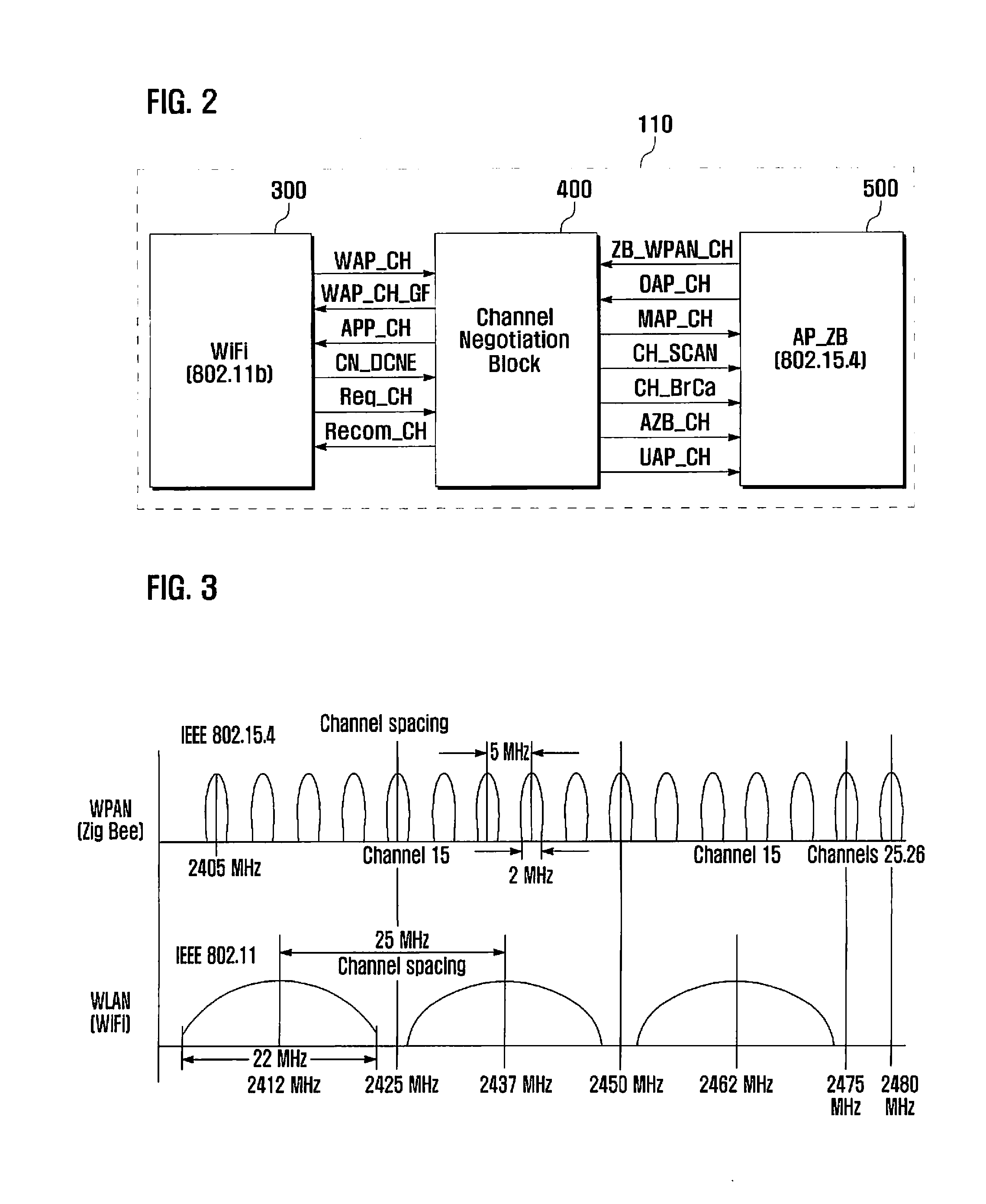
  • Summary
  • Abstract
  • Description
  • Claims
  • Application Information

AI Technical Summary

Benefits of technology

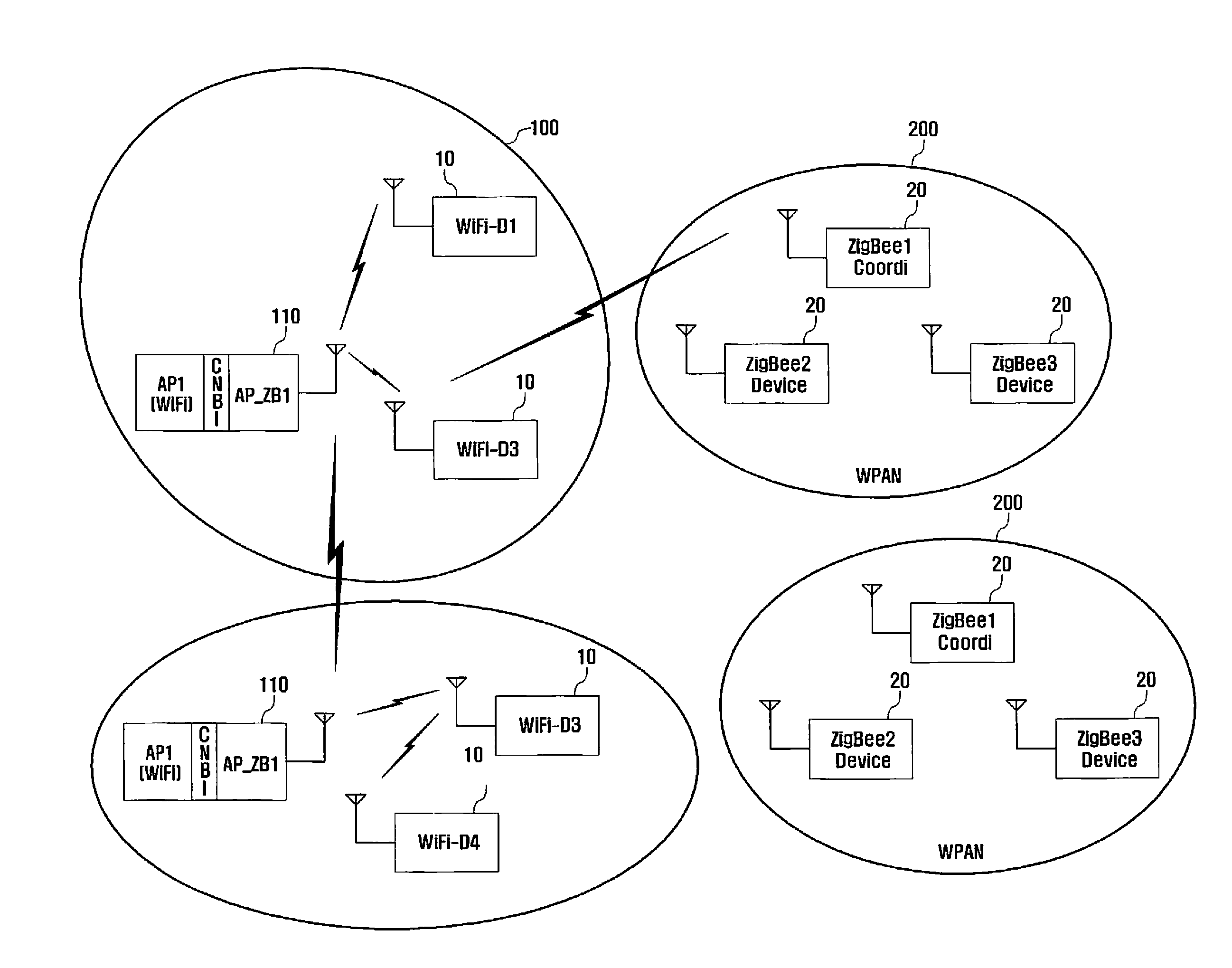
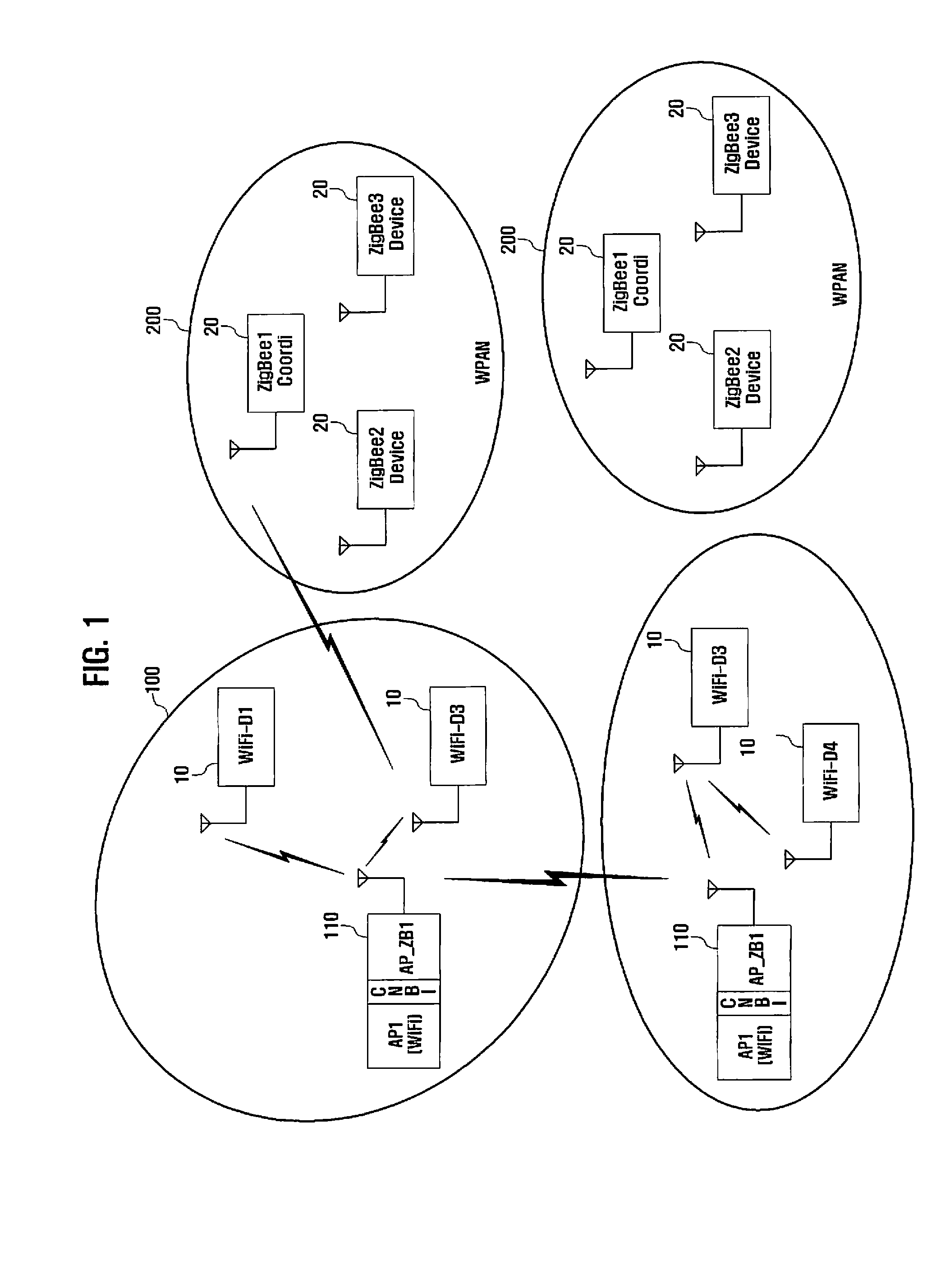
[0009]In order to overcome the problems of the prior art, the present invention provides a channel allocation method and apparatus that is capable of allocating the frequencies (channels) efficiently without transmission overlap between heterogeneous networks sharing a frequency band.

Problems solved by technology

Under these conditions, the transmissions can overlap and mutually interfere with each other, which causes severe system throughput degradation.
Currently, when two different technologies interfere with each other, the technology having the stronger transmission energy is likely to achieve successful transmission, while the technology having a weaker energy is likely to experience a severe degradation in system performance.

Method used


Image

  • Channel allocation method and apparatus for wireless communication networks
  • Channel allocation method and apparatus for wireless communication networks
  • Channel allocation method and apparatus for wireless communication networks

Examples


first embodiment

[0085]FIG. 8 illustrates a channel configuration method in a communication environment when a new WPAN is formed in a situation where multiple WPANs exist already according to the present invention.

[0086]FIG. 8 is depicted under the assumption that a WLAN AP forms a WPAN in a situation where the WPAN1201, WPAN2202, and WPAN3103 are operating. That is, the AP4104 switches on in an area where the WPAN1201, WPAN2202, and WPAN3103 are already deployed.

[0087]Referring to FIG. 8, once the AP4104 is switched on, it scans WLAN and WPAN channels and finds the adjacent networks (including WLANs and WPANs) that are currently operating, i.e. WPAN1201, WPAN2202, and WPAN 103. At this time, the AP4105 can join each of the WPAN1201, WPAN2202, and WPAN3130 as a node of the respective WPANs 201, 202, and 103 to acquire channel information.

[0088]That is, the AP4104 joins the WPAN1201 as a WPAN device by means of the WPAN channel processor 500 (S801) and receives the channel information from the WPAN1...

second embodiment

[0091]FIGS. 9 and 10 illustrate a channel configuration method in a communication environment when a new WPAN is formed in a situation where multiple WPANs exist already according to the present invention.

[0092]FIGS. 9 and 10 are depicted under the assumption that a WLAN AP forms a WPAN in a situation whether the WPAN1201, WPAN2202, WPAN3103, and WPAN4104 are operating. That is, the AP5105 switches on in an area where the WPAN1201, WPAN2202, WPAN3103, and WPAN4104 are already deployed.

[0093]Referring to FIGS. 9 and 10, once the AP5105 is switched on, it scans WLAN and WPAN channels and finds the adjacent networks (including WLANs and WPANs) that are currently operating, i.e. WPAN1201, WPAN2202, WPAN3103, and WPAN4104. At this time, the AP 5 can join each of the WPAN1201, WPAN2202, WPAN3103, and WPAN4104 as a node of the respective WPANs 201, 202, 103, and 104 to acquire channel information.

[0094]That is, the AP5105 joins the WPAN1201 as a WPAN device by means of the WPAN channel pro...


PUM


Abstract

A channel allocation method for use in a wireless communication environment, where Wireless Local Area Networks (WLANs) and Wireless Personal Area Networks (WPANs) coexist, includes collecting, at an access point, information on channels used by the WLANs and WPANs, determining available WLAN channels and available WPAN channels based on the channel information, allocating one of the available WLAN channels and one of the available WPAN channels to the access point, and informing the WLANs and WPANs of the allocated WLAN and WPAN channels.

Description

PRIORITY[0001]This application claims priority under 35 U.S.C. 119 to an application entitled “CHANNEL ALLOCATION METHOD AND APPARATUS FOR WIRELESS COMMUNICATION NETWORKS” filed in the Korean Intellectual Property Office on Oct. 13, 2008 and assigned Serial No. 10-2008-0100312, the contents of which are incorporated herein by reference.BACKGROUND OF THE INVENTION[0002]1. Field of the Invention[0003]The present invention relates generally to a wireless communication system and, in particular, to a channel allocation method and apparatus for avoiding internetwork interference in a communication environment where heterogeneous wireless communication networks coexist.[0004]2. Description of the Related Art[0005]The 2.4 GHz Industrial, Scientific, and Medical (ISM) band is shared by different wireless communication technologies such as WiFi, Bluetooth®, and ZigBee®, for a Wireless Local Area Network (WLAN) and Wireless Personal Area Network (WPAN).[0006]Such communication technologies ar...

Claims


Application Information

Patent Timeline
IPC IPC(8): H04W72/04
CPCH04W16/14H04W88/10H04W84/12H04W24/00H04W72/04
Inventor KIM, SUNG MINKIM, CHUL JINLEE, EUN HWAKIM, JUNG HYEONHUR, JI HYE
Owner SAMSUNG ELECTRONICS CO LTD
Learn More