Spinal connection assembly

a technology of connecting parts and connecting parts, which is applied in the field of connecting parts of the spine, can solve the problems of affecting the operation efficiency of the spine, the prominence of the total structure, and the limited amount of rotation

Active Publication Date: 2010-04-15
TOTAL CONNECT SPINE
View PDF87 Cites 55 Cited by
  • Summary
  • Abstract
  • Description
  • Claims
  • Application Information

AI Technical Summary

Benefits of technology

[0011]A low-profile side-by-side spinal connection assembly for use with a posterior spinal connector having a head and a groove adjacent the head for providing a neck and a connector element to treat a spine of a mammalian body is provided. The assembly includes a housing having first and second side portions and a top and a bottom. The first side portion is provided with a bottom-facing first opening adapted for receiv...

Problems solved by technology

Unfortunately, problems exist with each of the aforementioned systems.
Thus, a pedicle or other posterior spinal screw having a tulip on top of it increases the distance between the pedicle screw head and the top of the mechanism that askews a rod, causing prominence of the total construct.
Additionally, only a limited amount of rotation is permitted due to the geometry of currently used tulip devices.
This causes preload on the pedicle screws within the pedicle.
Moreover, a torquing of the pedicle may result as the physician forces the rod capturing screw on top of the tulip or screw, which then causes torsional stresse...

Method used


Image

  • Spinal connection assembly
  • Spinal connection assembly
  • Spinal connection assembly

Examples


Embodiment Construction

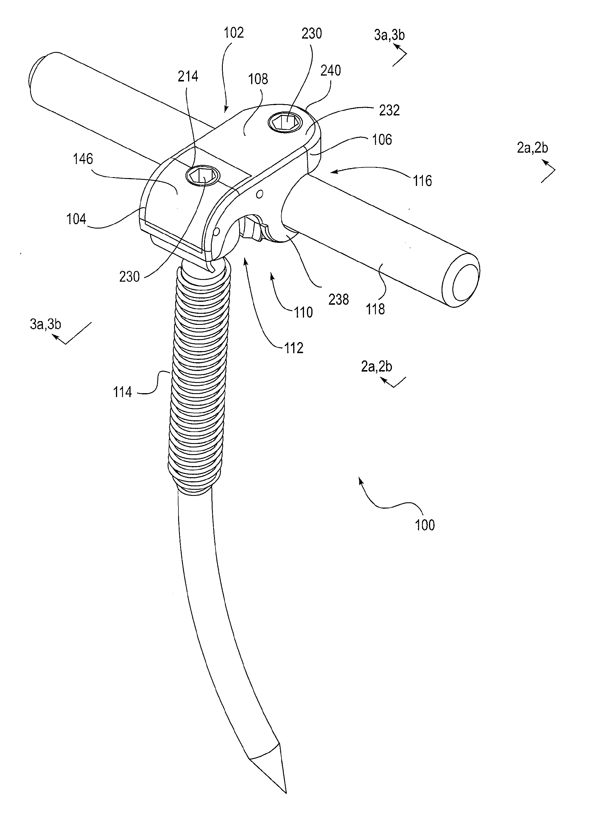
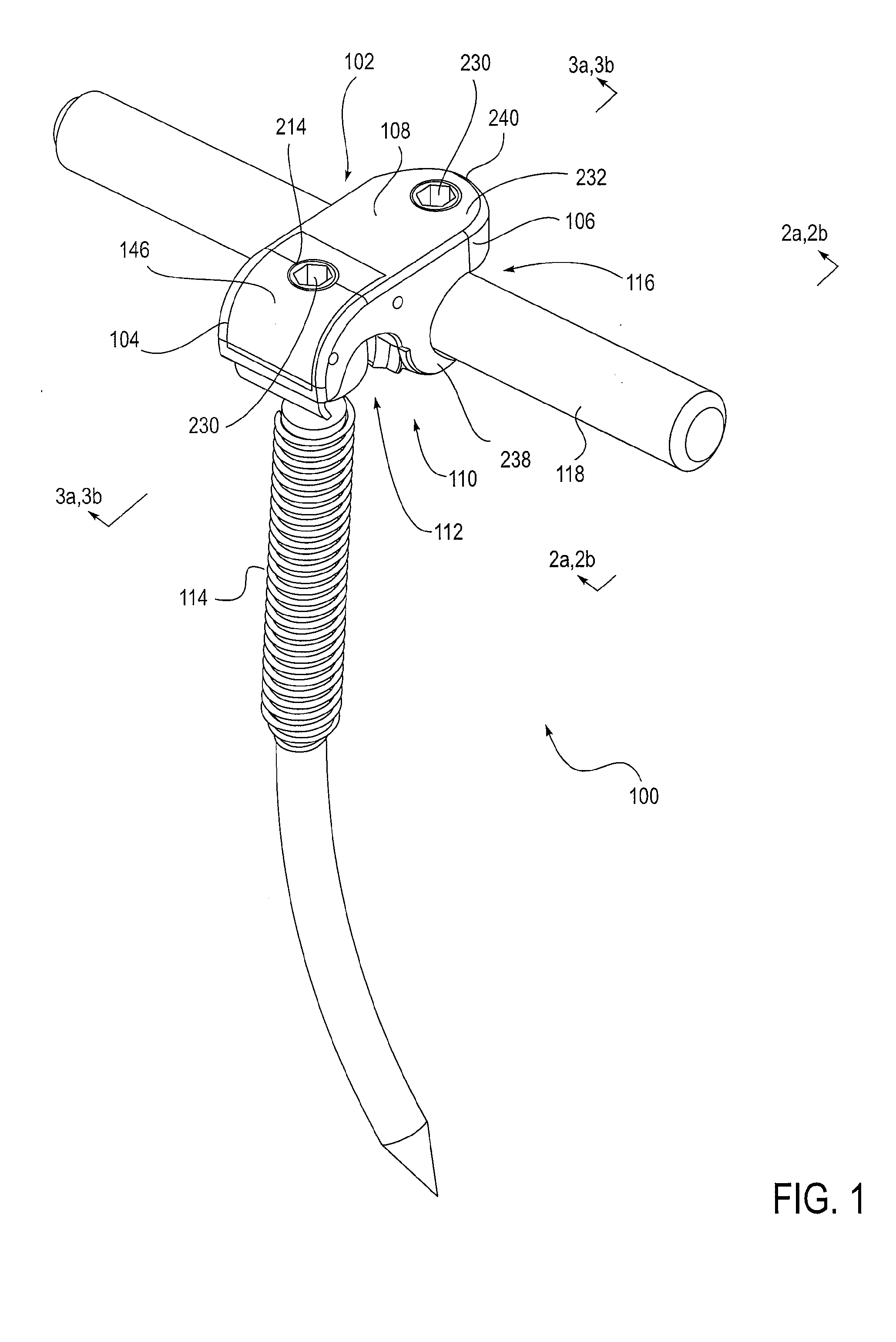
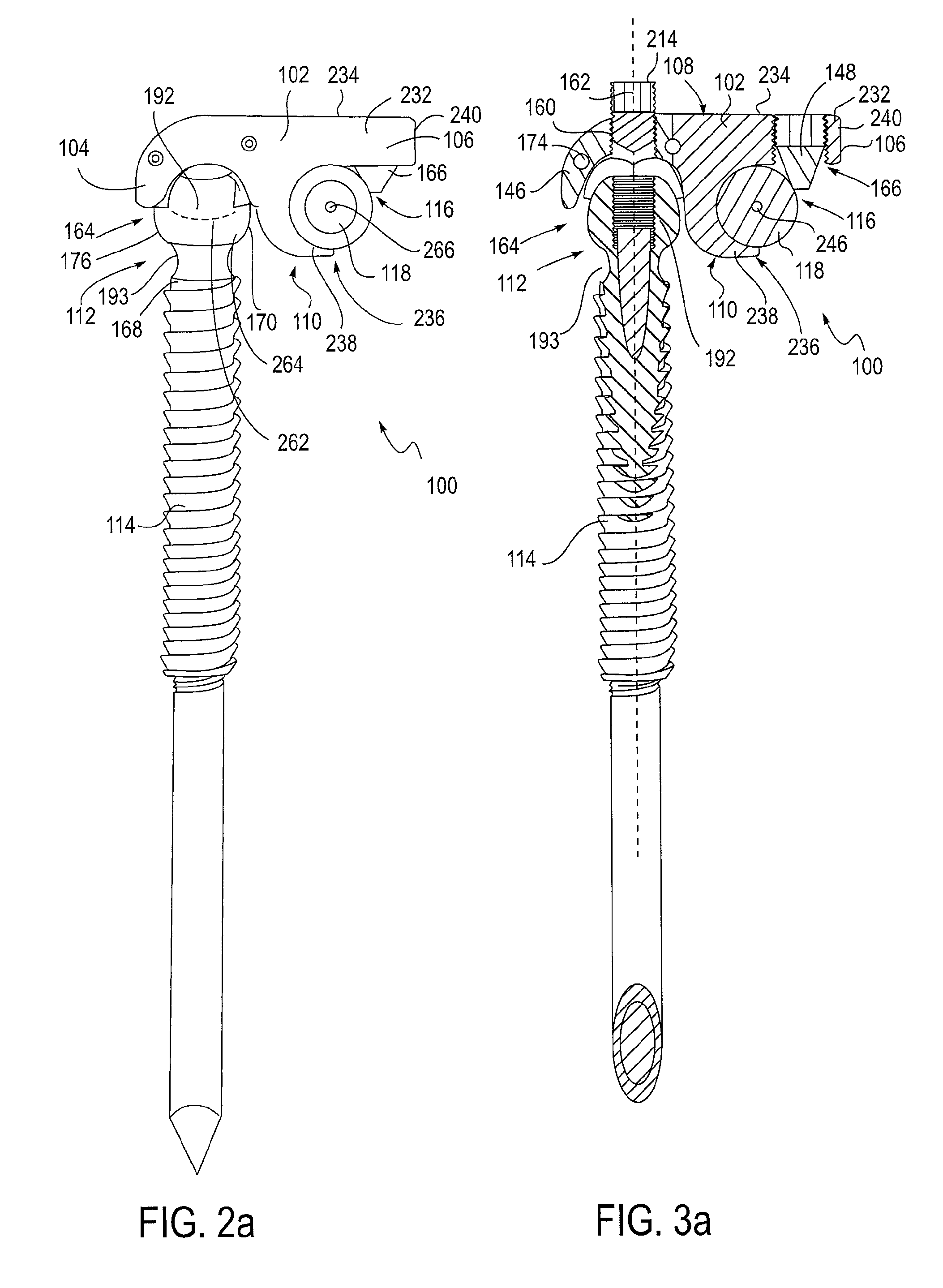
[0075]The invention is generally directed to a spinal connection assembly. More, specifically, a system for stabilizing adjacent vertebra in the mammalian spine is provided. The system disclosed generally includes a casing or housing having a portion to capture a first connector element, such as but not limited to a posterior spinal connector, and a portion to capture a second connector element, such as but not limited to a rod or second posterior spinal connector.

[0076]The spinal connection assemblies described herein and their individual components and respective attachments and securing devices, as well as the rods, posterior spinal connectors and cross-link members described herein may be made of any suitable material for use in the mammalian body, and preferably for use in association with the spine, such as but not limited to, stainless steel, titanium, vitalium, cobalt chrome, nitenol, carbon fiber, polyetheretherketone, plastics, biodegradable materials, bioeluting materials...


PUM


Abstract

A spinal connection assembly for use with a posterior spinal connector having a head and a groove adjacent the head for providing a neck and a connector element to treat a spine of a mammalian body is provided. The assembly includes a housing having first and second side portions and a top and a bottom. The first side portion is provided with a bottom-facing first opening adapted for receiving the posterior spinal connector. A capture mechanism is carried by the first side portion for engaging the head of the posterior spinal connector and extends at least partially into the groove so as to capture the head within the first opening. The second side portion is provided with a second opening. A securement mechanism is carried by the second side portion for capturing the connector element within the second opening.

Description

CROSS-REFERENCE TO RELATED APPLICATIONS[0001]This application claims the benefit of related U.S. Provisional Patent Application Ser. No. 61 / 104,104 filed Oct. 9, 2008, the entire content of which is hereby incorporated by this reference.SCOPE OF THE INVENTION[0002]The present invention relates to medical implants and in particular to spinal connection assemblies.BACKGROUND[0003]As is known, spinal fusions can be utilized when there is a deformity of the spine, instability of the spine, a damaged intervertebral disk, trauma to the spine, a tumor on the spine, spinal pain or infection or degeneration of the spine. A number of posterior spinal fixation methods are available for stabilizing the spine and permitting fusion to occur. Commonly, these devices are adapted for use with posterior spinal screws that are inserted into the vertebrae.[0004]A tulip is often provided on the posterior end of the posterior spinal screw for coupling the screw to a transverse rod that extends vertically...

Claims


Application Information

Patent Timeline
IPC IPC(8): A61B17/70
CPCA61B17/7038A61B17/7041A61B17/7044A61B17/8635A61B17/8605A61B17/863A61B17/7049
Inventor MATITYAHU, AMIR M.
Owner TOTAL CONNECT SPINE
Why Eureka
Try Eureka