Interlocking bone screw and washer concepts

a technology of interlocking bone screws and washers, which is applied in the field of surgically implantable spinal or other anatomical assemblies, can solve the problems that the use of such a transfacet bolt can be clumsy depending on the application, and there are no alternative devices or assemblies available or in existen

Active Publication Date: 2010-04-15
CTL MEDICAL CORP
View PDF16 Cites 60 Cited by
  • Summary
  • Abstract
  • Description
  • Claims
  • Application Information

AI Technical Summary

Benefits of technology

[0004]In an exemplary embodiment of the present invention, a cannulated bone screw system includes a screw with a threaded portion, a non-threaded portion, and a first plurality of teeth spaced apart from a screw head; and a washer with an interior portion with a second plurality of teeth and an opening and an outer portion with a plurality of spikes. The first plurality of teeth are on an inferior convex surface; wherein the second plurality of teeth are on a superior concave surface; and wherein the first plurality of teeth and the second plurality of teeth are operable to mate to prevent the screw from backing out of the washer while allowing the cannulated bone screw system to conform/pivot in order to accommodate different bone morphologies. The screw head can include keyed flanged heads. The cannulated bone screw system can further include a screw holder operable to engage the keyed flanged heads. Optionally, the cannulated bone screw system further includes a screw holder assembly disposed to the screw holder. Alternatively, the cannulated bone screw system further includes a rescue screw assembly disposed to the screw holder. The plurality of spikes are operable to engage a bone. The screw can be driven into the washer positioned at a pilot hole in a bone at an angle. Optionally, the bone includes a first facet joint and a second facet joint; wherein the pilot hole is located on the first facet joint; wherein the plurality of spikes are engaged to the first facet joint; and wherein the threaded portion is positioned within the second facet joint. The cannulated bone screw system can further include a drill guide and washer holder comprising an end clasping mechanism. Optionally, the end clasping mechanism includes an inserter tube that contains the washer.
[0005]In another exemplary embodiment of the present invention, a cannulated bone screw system includes a screw ...

Problems solved by technology

However, not all spinal morphologies support the utilization of such a transfacet bolt, and the utilization of such a transfacet bol...

Method used


Image

  • Interlocking bone screw and washer concepts
  • Interlocking bone screw and washer concepts
  • Interlocking bone screw and washer concepts

Examples


Embodiment Construction

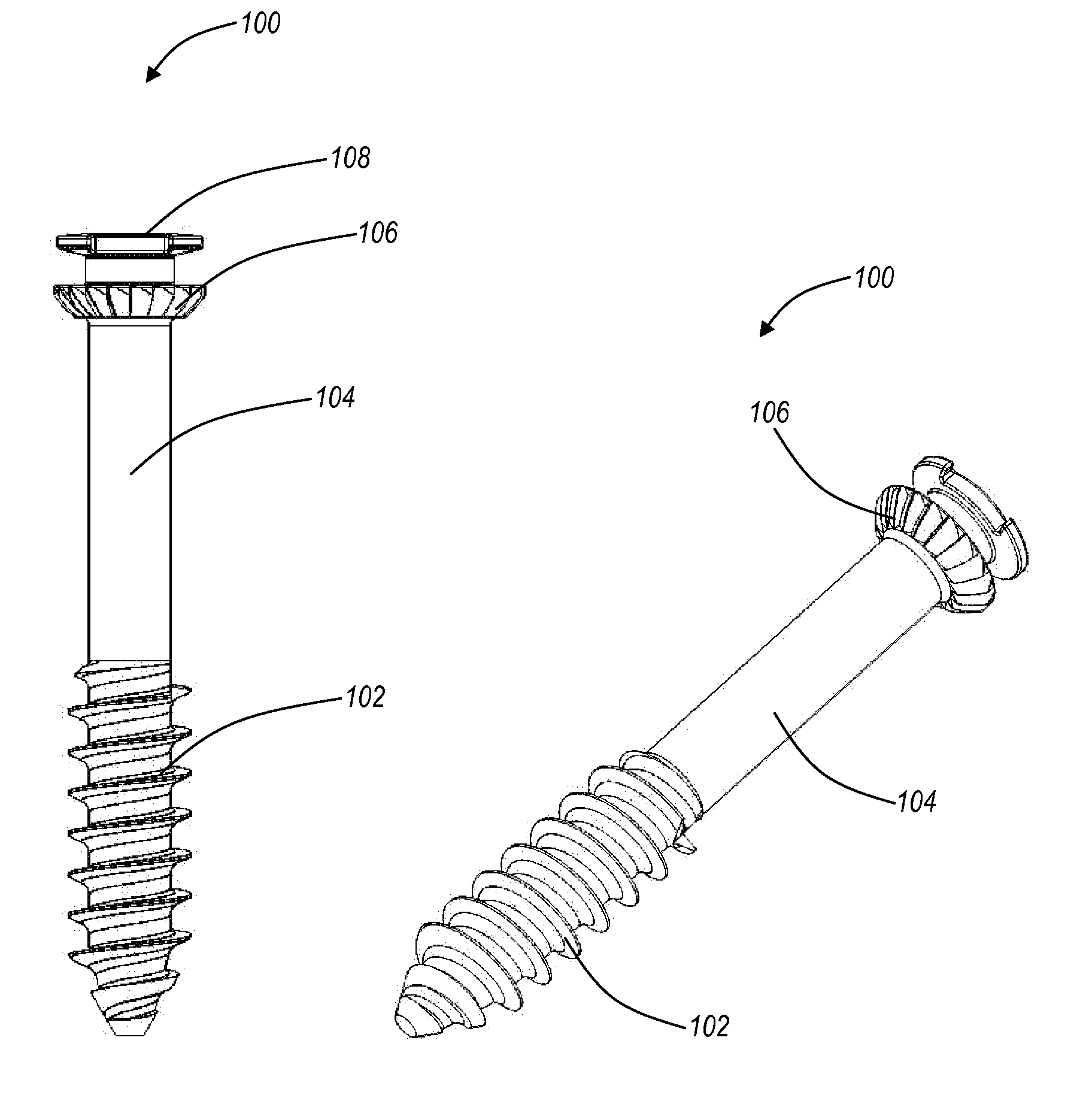
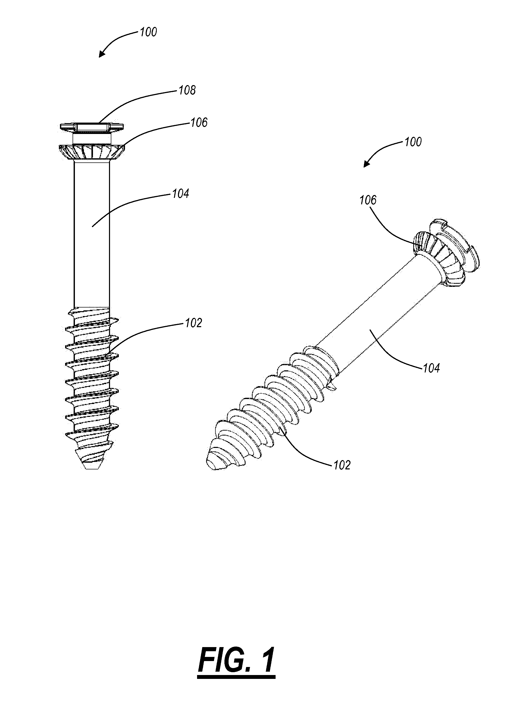
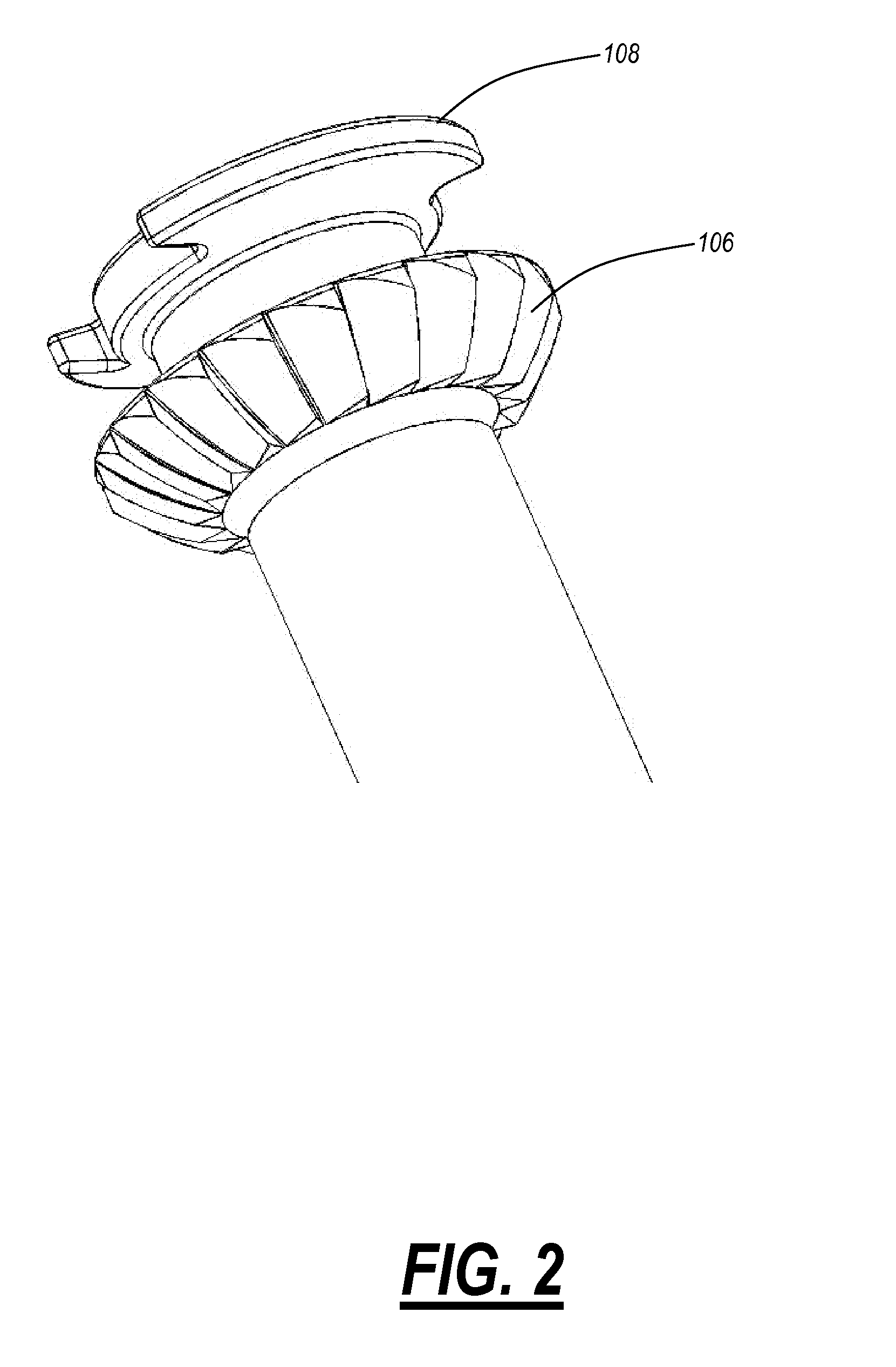
[0023]Referring to FIG. 1, different views are illustrated of a cannulated bone screw 100 according to an exemplary embodiment of the present invention. The cannulated bone screw 100 includes a threaded end portion 102, a non-threaded portion 104, and a radial interlocking convex toothed surface 106 disposed near a screw head 108. The threaded end portion 102 is operable to screw into a bone, such as a facet joint or the like. The cannulated bone screw 100 can be utilized to stabilize facet joints through an angular insertion of the cannulated bone screw 100 into a first facet and screwing the cannulated bone screw 100 into a second facet, the associated pedicle, or any other bony structure. Once fully engaged between the facets, the associated pedicle, or any other bony structure, the threaded portion 102 is embedded in the second facet, the associated pedicle, or any other bony structure, and the non-threaded portion 104 is in the first facet. Additionally, a washer (FIG. 3) is op...


PUM


Abstract

The present disclosure provides a cannulated bone screw system including a screw with a threaded portion, a non-threaded portion, and a first plurality of teeth spaced apart from a screw head; and a washer with an interior portion with a second plurality of teeth and an opening and an outer portion with a plurality of spikes. The first plurality of teeth are on an inferior convex surface; wherein the second plurality of teeth are on a superior concave surface; and wherein the first plurality of teeth and the second plurality of teeth are operable to mate to prevent the screw from backing out of the washer while allowing the cannulated bone screw system to conform/pivot in order to accommodate different bone morphologies.

Description

CROSS-REFERENCE TO RELATED APPLICATION(S)[0001]The present non-provisional patent application / patent claims the benefit of priority of co-pending U.S. Provisional Patent Application No. 61 / 105,545, filed on Oct. 15, 2008, and entitled “INTERLOCKING BONE SCREW AND WASHER CONCEPTS,” the contents of which are incorporated in full by reference herein.FIELD OF THE INVENTION[0002]The present invention relates generally to a surgically-implantable spinal or other anatomical assembly. More specifically, the present invention relates to a cannulated bone screw system that includes a screw with a threaded portion, a non-threaded portion, and a first plurality of teeth spaced apart from a screw head; and a washer with an interior portion with a second plurality of teeth and an opening and an outer portion with a plurality of spikes. The cannulated bone screw system can be used to immobilize a facet joint of the spine, for example.BACKGROUND OF THE INVENTION[0003]In various cases, it is desirab...

Claims


Application Information

Patent Timeline
IPC IPC(8): A61B17/86
CPCA61B17/862A61B17/8695A61B17/8872A61B2017/8655A61B17/8605A61B17/864A61B17/8891
Inventor VARELA, ARMANDOBLAKE, DORISCAWLEY, TRACEHARRIS, PETER
Owner CTL MEDICAL CORP
Why Eureka
Try Eureka