Electronic mechanical drum brake

a technology of electronic mechanical drum brake and drum brake, which is applied in the direction of mechanically actuated drum brake, combination drum brake, mechanical apparatus, etc., can solve the problems of increasing the number of necessary parts and raising manufacturing costs, and achieves the effects of generating a large braking power, improving space efficiency, and simple mechanical configuration

Active Publication Date: 2010-04-22
HL MANDO CORP
View PDF1 Cites 23 Cited by
  • Summary
  • Abstract
  • Description
  • Claims
  • Application Information

AI Technical Summary

Benefits of technology

[0011]Therefore, it is one aspect of the present invention to provide an electronic mechanical drum brake, which performs brak

Problems solved by technology

That is, in order to perform a braking function, the braking apparatus having the wedge structure requires the driving

Method used


Image

  • Electronic mechanical drum brake
  • Electronic mechanical drum brake
  • Electronic mechanical drum brake

Examples


Embodiment Construction

[0024]Reference will now be made in detail to the embodiments of the present invention, examples of which are illustrated in the accompanying drawings, wherein like reference numerals refer to like elements throughout.

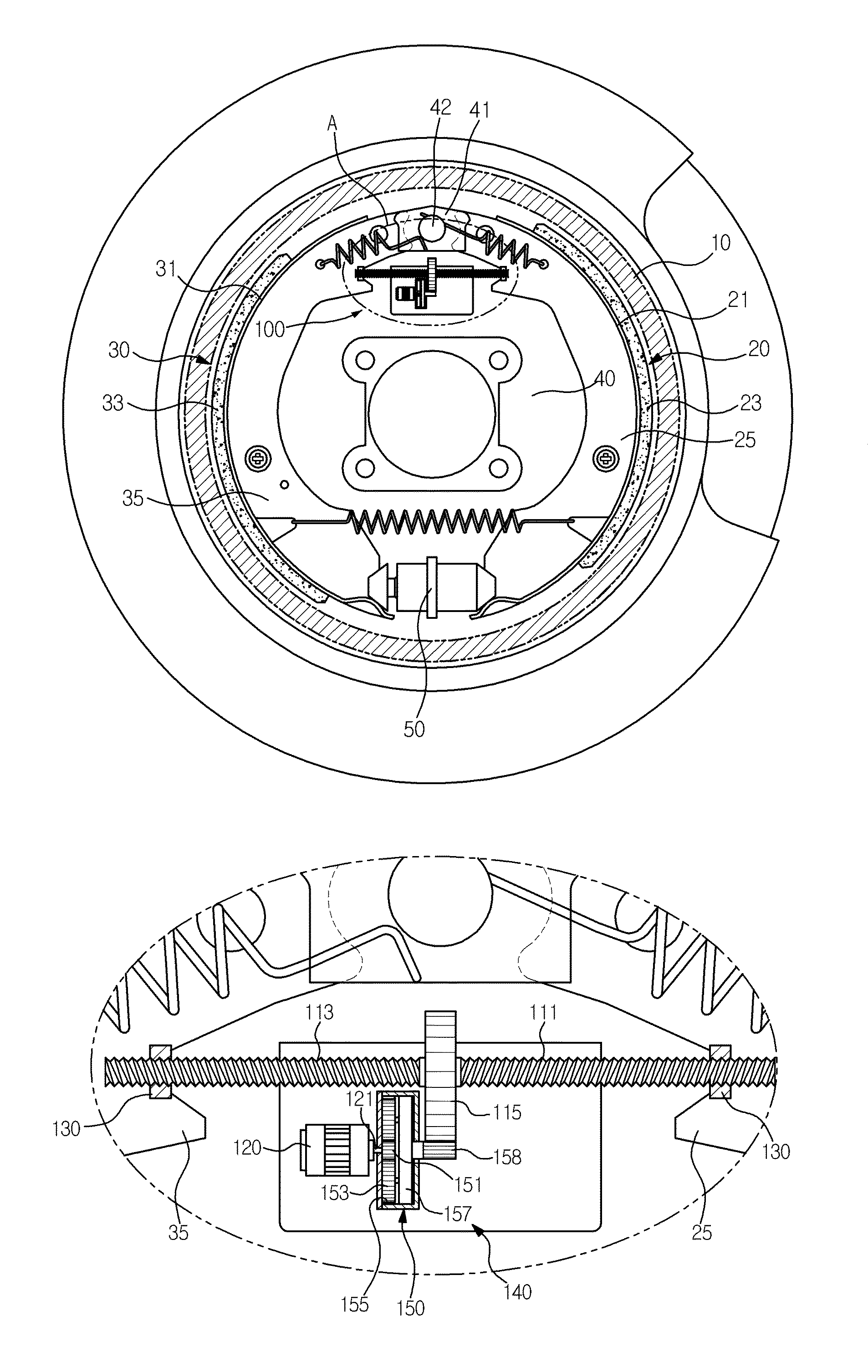
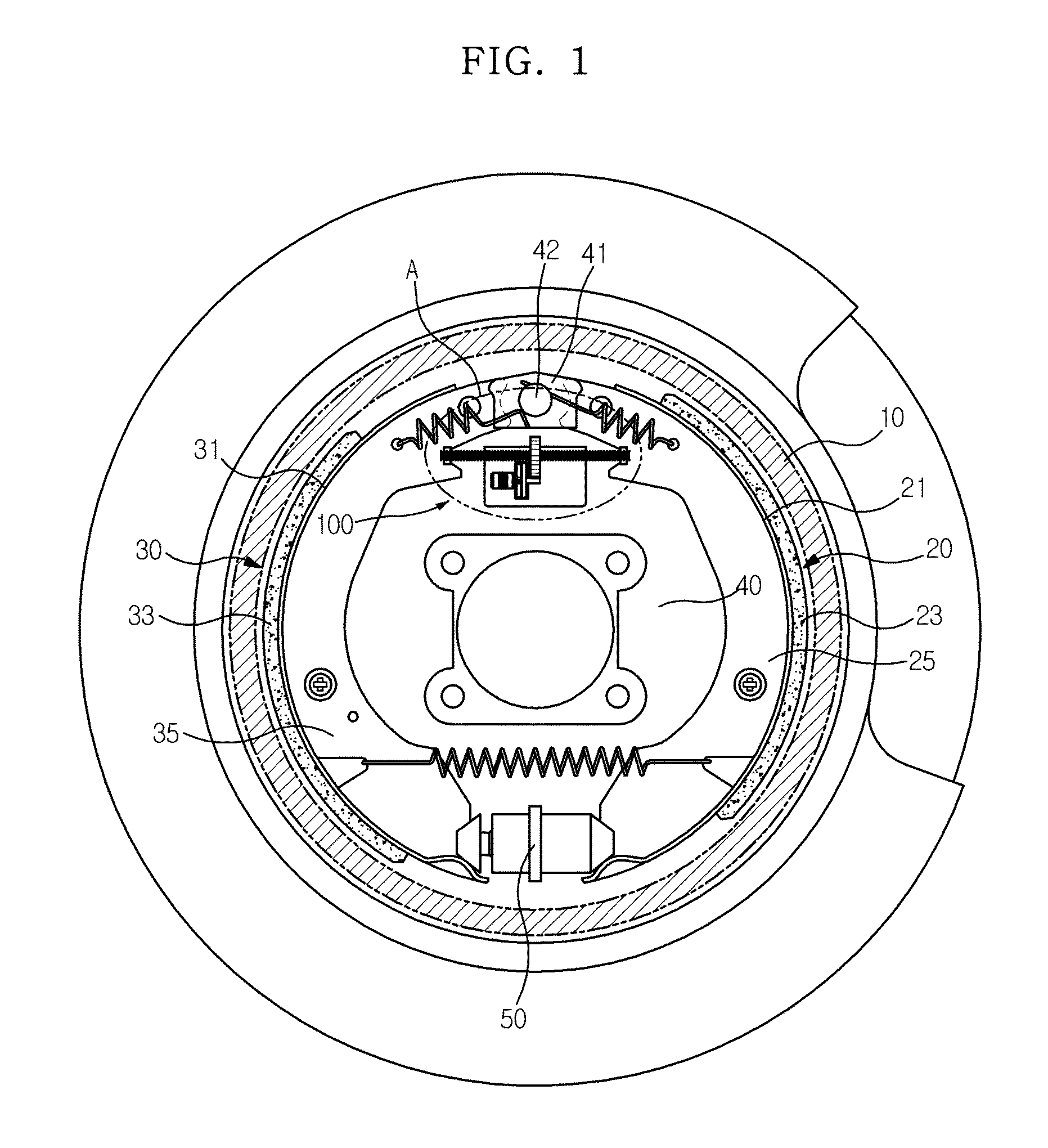
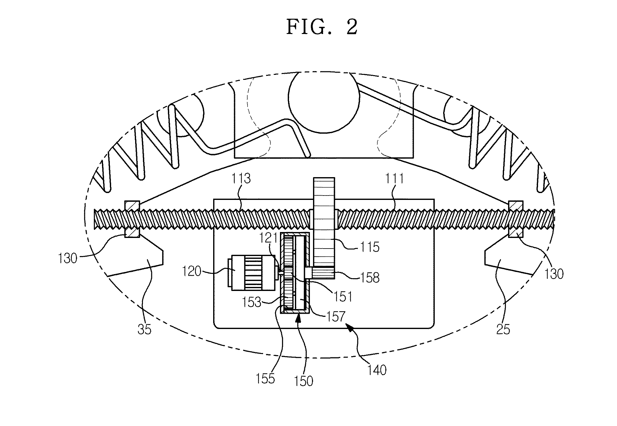
[0025]FIG. 1 is a cross-sectional view illustrating a schematic structure of an electronic mechanical drum brake in accordance with one embodiment of the present invention, and FIG. 2 is an enlarged view of a portion A of FIG. 1.

[0026]The electronic mechanical drum brake in accordance with this embodiment includes, as shown in FIG. 1, a drum 10 rotated together with a wheel (not shown), and a pair of brake shoes 20 and 30 having a semicircular shape and installed at both sides of the inner surface of the drum 10.

[0027]The two brake shoes 20 and 30 are mounted on a back plate 40 connected to a knuckle part (not shown) of a frame of a vehicle such that the brake shoes 20 and 30 are externally operatable, and are closely adhered to the inner circumferential surface of the...


PUM


Abstract

Disclosed herein is an electronic mechanical drum brake. In the electronic mechanical drum brake including a drum rotated together with a wheel, a pair of brake shoes respectively including rims provided with linings, which rub against the inner circumferential surface of the drum and generate braking power, attached thereto and webs provided on the inner circumferential surfaces of the rims to reinforce rigidity of the rims, and an actuator provided between the webs of the pair of brake shoes, the actuator includes a screw shaft provided with a driven gear formed integrally therewith and a left-handed thread at one side thereof and a right-handed thread at the other side thereof, a driving motor to rotate the screw shaft in a regular direction and its reverse direction, a booster unit to increase rotary force of the driving motor and then to transmit the increased rotary force to the driven gear, and nuts screw-connected to both ends of the screw shaft and fixed to the webs. Thereby, the electronic mechanical drum brake has a large braking power and improved space efficiency.

Description

CROSS-REFERENCE TO RELATED APPLICATION[0001]This application claims the benefit of Korean Patent Application No. 2008-0102839, filed on Oct. 21, 2008 in the Korean Intellectual Property Office, the disclosure of which is incorporated herein by reference.BACKGROUND[0002]1. Field[0003]Embodiments of the present invention relate to an electronic mechanical drum brake with an electronic mechanical braking apparatus, which generates braking power using a motor.[0004]2. Description of the Related Art[0005]In general, brakes mounted in vehicles serve to decelerate or stop a vehicle during driving or maintain a stopped state of the vehicle, and perform a braking action by changing kinematic energy of the vehicle during driving into heat energy using a mechanical friction device.[0006]These brakes are generally divided into drum brakes and disc brakes, and perform a braking action by an oil pressure.[0007]Recently, an electronic mechanical braking apparatus, which performs a braking action b...

Claims


Application Information

Patent Timeline
IPC IPC(8): F16D51/22F16D65/28
CPCF16D51/48F16D2121/24F16D2125/50F16D2125/48F16D2125/40F16D53/00F16D65/04F16D65/28
Inventor KIM, JOO GON
Owner HL MANDO CORP
Why Eureka
Try Eureka