
Liquid crystal display

a liquid crystal display and display luminance technology, applied in the field of liquid crystal display devices, can solve the problems of uneven luminance and display luminance according to viewing direction, and achieve the effect of minimizing the deterioration of display quality

Active Publication Date: 2010-04-22
SHARP KK
View PDF63 Cites 66 Cited by
  • Summary
  • Abstract
  • Description
  • Claims
  • Application Information

AI Technical Summary

Benefits of technology

[0050]The present invention provides a liquid crystal display device that can minimize deterioration in display quality even when the source line inversion drive method or the block inversion drive method is applied to the multi-pixel technology.

Problems solved by technology

Such a variation in display luminance corresponding to grayscale according to the viewing direction would be a problem particularly when a still picture such as a photo or a TV broadcast is presented on the LCD.
As a result, the display luminance will depend on the location within the display area, thus possibly making the luminances uneven.

Method used


Image

  • Liquid crystal display
  • Liquid crystal display
  • Liquid crystal display

Examples


Embodiment Construction

[0113]Hereinafter, a configuration for a liquid crystal display device as a preferred embodiment of the present invention and how to drive it will be described with reference to the accompanying drawings. However, the present invention is in no way limited to the specific preferred embodiment to be described below.

[0114]Source Line Inversion

[0115]First of all, it will be described in detail with reference to FIGS. 43 through 45B and FIGS. 46 through 48B what problems the present inventors discovered would arise if the source line inversion drive method was applied to the multi-pixel technology.

[0116]Now it will be described with reference to FIGS. 43 through 45B what if the liquid crystal display device with the multi-pixel structure disclosed in Patent Document No. 2 is driven by the dot inversion drive technique.

[0117]FIG. 43 schematically illustrates how pixels of the liquid crystal display device disclosed in Patent Document No. 2 are connected to CS bus lines along with the pol...


PUM


Abstract

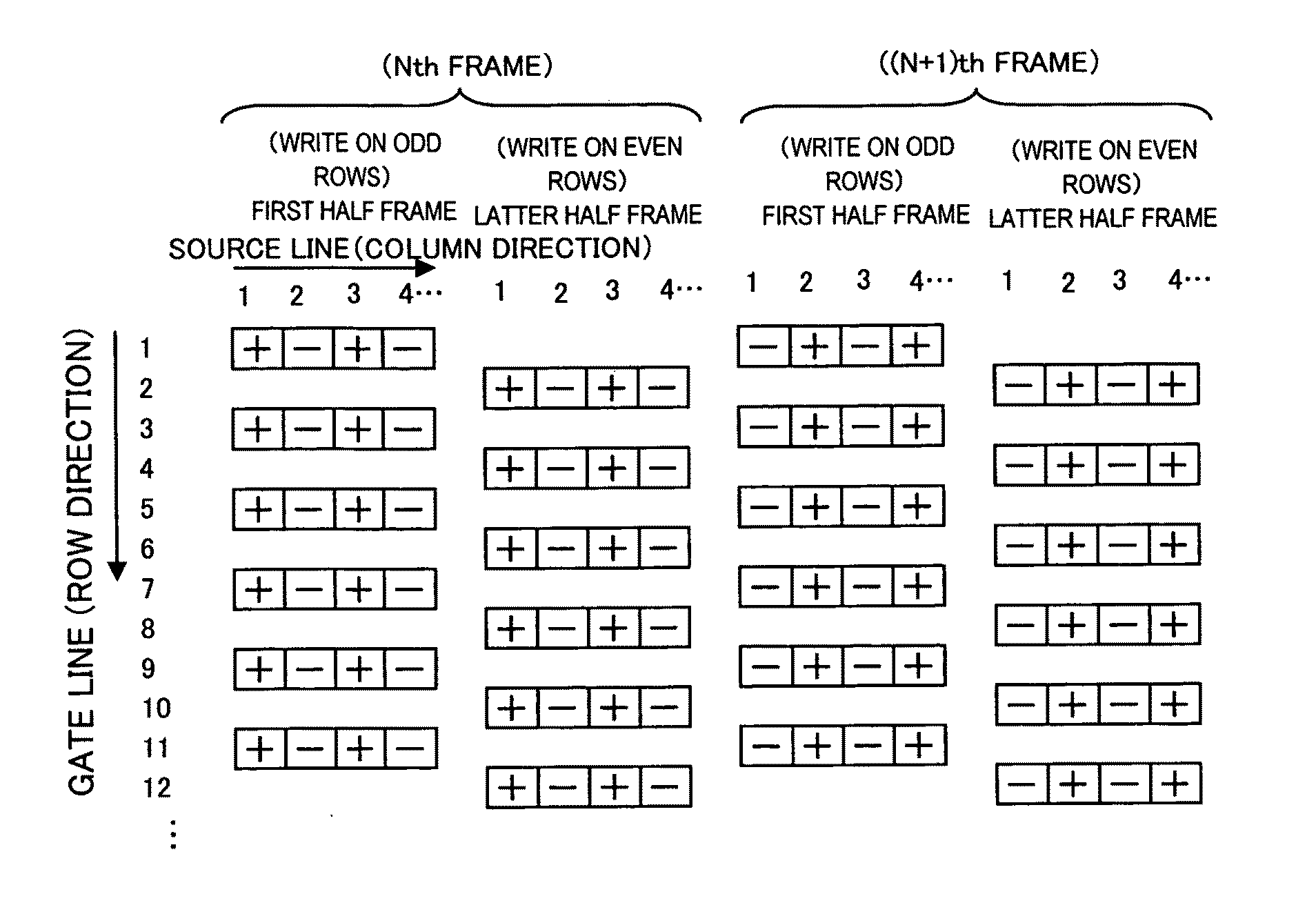
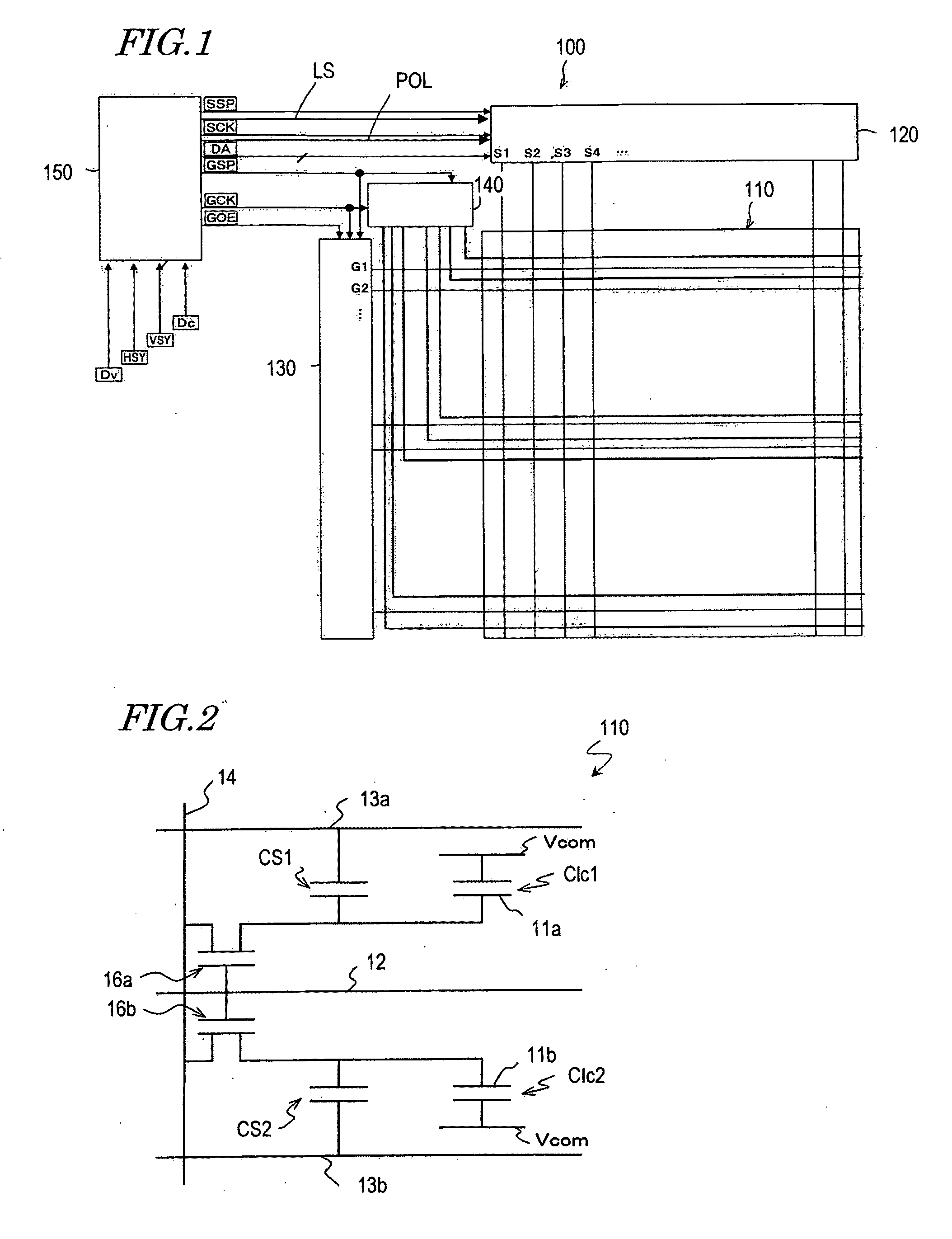
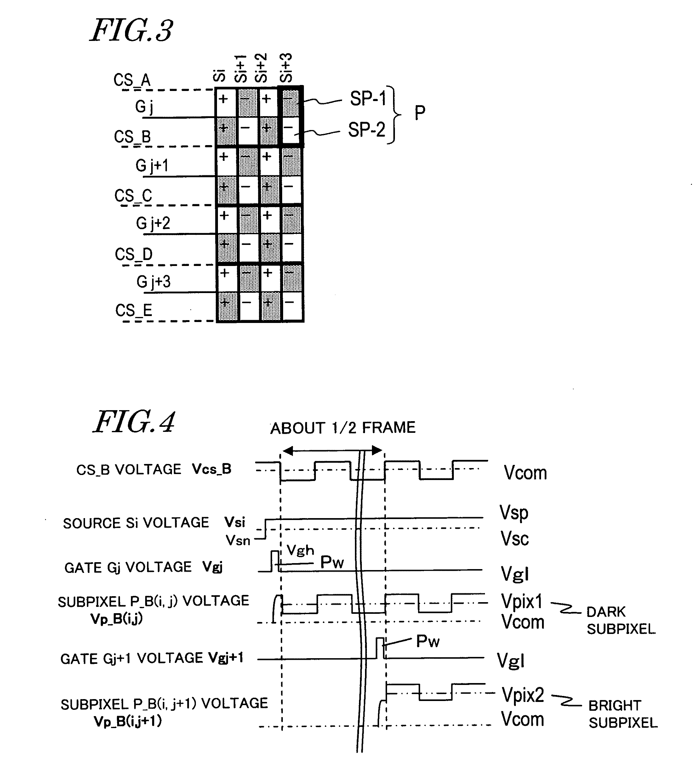
In one embodiment of the present invention, each pixel includes first and second subpixels. CS bus lines connected to the respective storage capacitors of the first and second subpixels are electrically independent of each other. A CS voltage has a waveform that inverts its polarity at least once a frame, which includes a first subframe for sequentially scanning a series of odd rows and a second SF for sequentially scanning even rows that have been skipped during the first SF. A source signal voltage varies so as to have two frames or subframes with mutually opposite polarities. A CS voltage has a waveform that has quite opposite consequences on the effective voltage of a subpixel of a pixel connected to the jth scan line to be selected during the first subframe and on that of another subpixel of a pixel connected to the (j+1)th scan line to be selected during the second subframe. In this manner, the deterioration in display quality, which would be caused if either a source line inversion drive or a block inversion drive is applied to a multi-pixel technology, can be minimized.

Description

TECHNICAL FIELD[0001]The present invention relates to a liquid crystal display device and more particularly relates to a liquid crystal display device that exhibits a wide viewing angle characteristic using a multi-pixel structure.BACKGROUND ART[0002]Recently, a multi-domain vertical aligned (MVA) mode LCD has been developed as a liquid crystal display device with improved viewing angle characteristic and used in LCD TV sets, among other things. A VA mode LCD conducts a display operation in normally black mode by using, in combination, a vertical alignment liquid crystal layer, in which liquid crystal molecules are aligned perpendicularly to the substrate surface when no voltage is applied thereto, and two polarizers that are arranged as crossed Nicols with the liquid crystal layer interposed between them.[0003]As disclosed in Patent Document No. 1, an MVA mode LCD defines the falling directions of liquid crystal molecules upon the application of a voltage by providing linear domain...

Claims


Application Information

Patent Timeline
Patent Type & Authority Applications(United States)
IPC IPC(8): G09G3/36G06F3/038
CPCG02F1/133707G02F1/1362G02F2201/122G02F2201/123G09G3/3614G09G3/3655G09G2310/08G09G3/3677G09G2300/0443G09G2300/0447G09G2300/0876G09G2310/0224G09G3/3666G02F1/134336G02F1/1368G09G3/2077G09G3/3688G09G2300/0413G09G2300/0426G09G2310/0286G09G2310/06G09G2320/0233G11C19/00G02F1/134345
Inventor KITAYAMA, MASAESHIMOSHIKIRYOH, FUMIKAZUIRIE, KENTAROHTSUBATA, TOSHIHIDEYAMADA, NAOSHINAKAGAWA, HIDETOSHI
Owner SHARP KK
Learn More