Display apparatus

a technology of display apparatus and display screen, which is applied in the direction of printers, cameras, instruments, etc., can solve the problems of increasing the cost of the apparatus, reducing work efficiency, and difficult to grasp the positional relationship of the partial image with the overall picture, and achieves the effect of low cos

Active Publication Date: 2010-04-22
SEIKO EPSON CORP
View PDF4 Cites 18 Cited by
  • Summary
  • Abstract
  • Description
  • Claims
  • Application Information

AI Technical Summary

Benefits of technology

[0036]Thus, the advantage of realizing the same function as the high-resolution display at relatively low cost becomes prominent.

Problems solved by technology

Since the past, in work using CAD, simulations, and so on, there have been a lot of cases in which details of a partial image of a display image such as a design drawing is confirmed while confirming the overall picture thereof, and in the case in which a display with a general purpose pixel count such as XGA is used, it is required to repeat zooming in and zooming out of the display image, which incurs decrease in work efficiency.
Further, in the case in which the image is zoomed in for confirming the details of the partial image, the overall picture of the image becomes invisible, and therefore, it is difficult to grasp the positional relationship of the partial image with the overall picture.
However, in order for performing display based directly on the image signal with high pixel count, a projector provided with a light valve (e.g., a liquid crystal light valve) corresponding to the input image signal is required, which leads to incurring increase in apparatus cost.
On the other hand, in a display with a large screen, it is natural for the user to view the screen from a position distant from the display to some extent when viewing the overall picture, and from a position close to the display because of limitation in resolution of the eyesight when viewing details thereof.
In the Document 1 described above, details of the control of the size and the position of the display made by a local projection projector adapted to perform display of a partial detailed image, for example, are not at all disclosed, and therefore, the disclosure thereof is insufficient for coping with the problem described above.
Further, in either one of the Document 2 and the Document 3, since the size of the object varies in accordance with the observation distance, the size of the object thus displayed as described above does not vary, which is not suitable for the natural action of viewing the screen from a position closer thereto for confirming the details.
Further, the action thereof is adverse to the action of getting closer for viewing the details in such away that the object displayed thereon becomes larger as the observation distance increases and smaller as it decreases, which is not suitable for CAD, simulations, and so on.

Method used


Image

  • Display apparatus
  • Display apparatus
  • Display apparatus

Examples


first embodiment

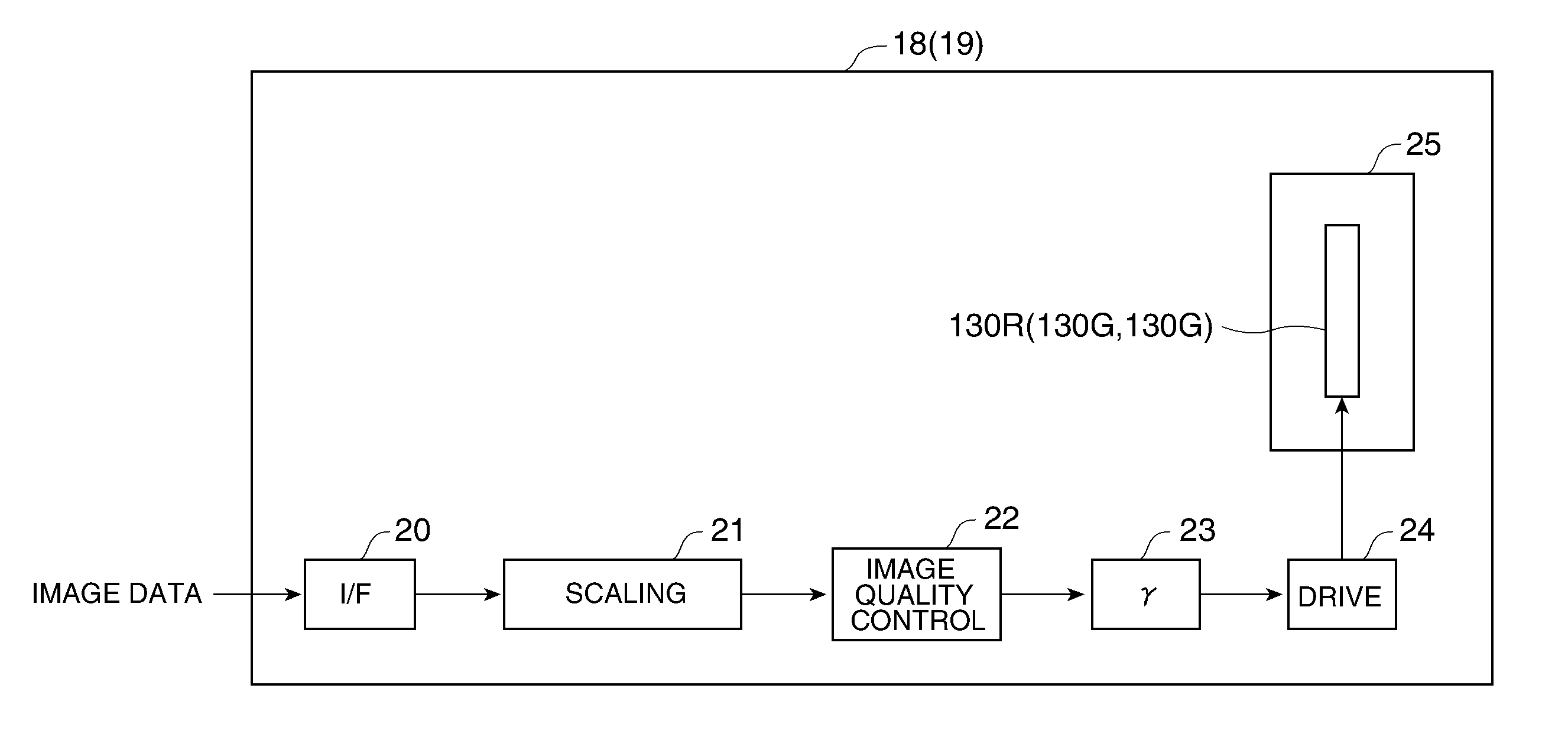
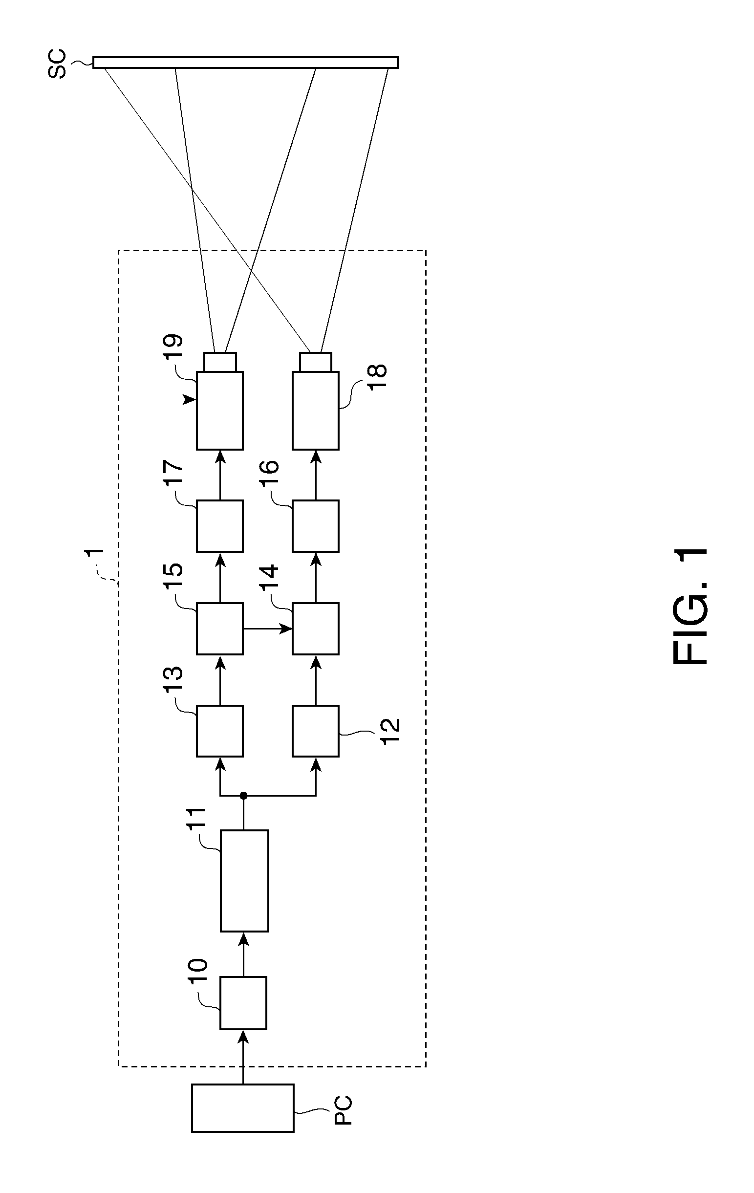
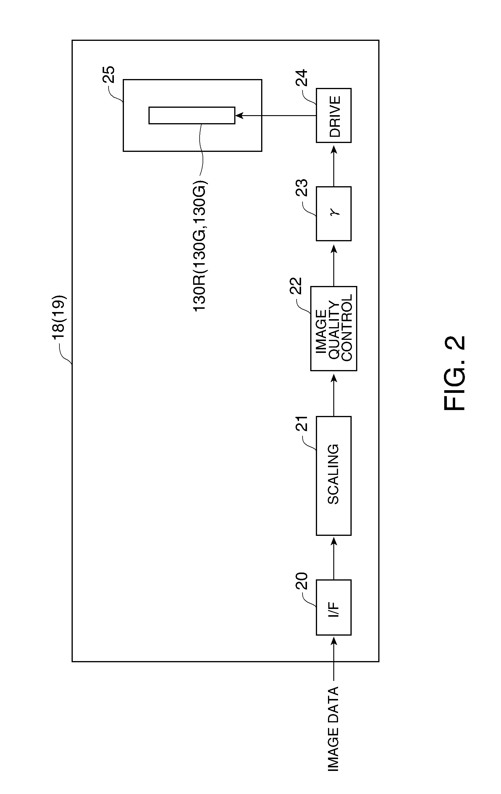
[0059]Firstly, a display apparatus according to a first embodiment of the invention will be explained. FIG. 1 is a schematic diagram of a configuration of the display apparatus 1 according to the first embodiment. As shown in FIG. 1, the present display apparatus 1 is composed of an A / D converter 10, an image memory 11, a first resolution conversion circuit 12, a second resolution conversion circuit 13, a first image buffer 14, a second image buffer 15, a first output circuit 16, a second output circuit 17, a first projector 18, and a second projector 19.

[0060]The display apparatus 1 thus configured is for projecting an image corresponding to the image signal input from a computer PC to display it on a screen SC. The computer PC is capable of processing the image signal, for example, of a personal computer or a DVD player. Further, the screen SC can be either one of a front screen observed from a projection side and a rear screen observed from an opposite side to the projection side...

second embodiment

[0092]Then, a display apparatus according to a second embodiment of the invention will be explained. The second embodiment relates to a display apparatus capable of varying the size of the projection window W2 by the second projector 19 in accordance with the distance from the screen SC to the observer.

[0093]FIG. 8 is a schematic diagram of a configuration of the display apparatus 2 according to the second embodiment. It should be noted that in FIG. 8, substantially the same constituents as those shown in FIG. 1 (the first embodiment) are denoted with the same reference numerals, and the explanations therefor will be omitted. As shown in FIG. 8, the display apparatus 2 in the second embodiment is additionally provided with an observation distance measurement section 30, an observation distance manually setting section 31, a switching circuit 32, and a parameter generation section 33.

[0094]The observation distance measurement section 30 measures the distance d from the screen SC to t...

third embodiment

[0130]Then, a display apparatus according to a third embodiment of the invention will be explained. In the first and the second embodiments described above, there is explained the case of displaying the projection window W2 of the second projector 19 at the center of the projection window W1 of the first projector 18, namely the case in which the centers of the projection windows W1, W2 are constantly the same. In contrast, the present third embodiment relates to a display apparatus capable of controlling the display position of the projection window W2 in accordance with the location of the observer with respect to the inside of the surface of the screen SC.

[0131]FIG. 13 is a schematic diagram of a configuration of the display apparatus 3 according to the third embodiment. It should be noted that in FIG. 13, substantially the same constituents as those shown in FIG. 1 or FIG. 8 are denoted with the same reference numerals, and the explanations therefor will be omitted. As shown in ...


PUM


Abstract

A display apparatus adapted to generate image data for controlling a first light modulation section adapted to project a first window, and image data for controlling a second light modulation section adapted to project a second window smaller than the first window and projected so as to overlap with the first window, includes: a first image conversion section adapted to convert a resolution of input image data in accordance a resolution of the first light modulation section to form the image data for controlling the first light modulation section; and a second image conversion section adapted to extract data included in a range corresponding to a resolution of the second light modulation section among the input image data to form the image data for controlling the second light modulation section.

Description

BACKGROUND[0001]1. Technical Field[0002]The present invention relates to a display apparatus, in particular to a display apparatus for projecting a first window with a first light modulation section and projecting a second window smaller than the first window with a second light modulation section in an overlapping manner.[0003]2. Related Art[0004]Since the past, in work using CAD, simulations, and so on, there have been a lot of cases in which details of a partial image of a display image such as a design drawing is confirmed while confirming the overall picture thereof, and in the case in which a display with a general purpose pixel count such as XGA is used, it is required to repeat zooming in and zooming out of the display image, which incurs decrease in work efficiency. Further, in the case in which the image is zoomed in for confirming the details of the partial image, the overall picture of the image becomes invisible, and therefore, it is difficult to grasp the positional re...

Claims


Application Information

Patent Timeline
Patent Type & Authority Applications(United States)
IPC IPC(8): G09G5/02G03B21/14G06F3/048G06F3/0484
CPCG03B21/14G09G2340/0407G09G5/14G03B21/26H04N9/3147H04N9/3188H04N9/3194
Inventor YONENO, KUNIO
Owner SEIKO EPSON CORP
Why Eureka
Try Eureka