
Optical interconnection modules for hybrid electrical-optical networks

a technology of optical interconnection and hybrid electrical optical network, applied in the field of optical fiber network, can solve the problems of utp cabling infrastructure that will need to be re-cabled, and the cost of optical interconnection equipment is typically three times more expensive than utp-enabled gigabit system equipmen

Active Publication Date: 2010-04-22
CORNING OPTICAL COMM LLC
View PDF70 Cites 23 Cited by
  • Summary
  • Abstract
  • Description
  • Claims
  • Application Information

AI Technical Summary

Problems solved by technology

Optics-enabled Gigabit system equipment is typically three times more expensive than UTP-enabled (i.e., electronics-enabled) Gigabit equipment.
While deploying the less expensive electronics-based system and cabling infrastructure is appealing, the risk is that once 10 Gigabit and 100 optics-based Gigabit system equipment is deployed, the UTP cabling infrastructure will need to be re-cabled with an optical fiber cabling infrastructure.
However, a complication arises in such an E-O hybrid network in that port “polarity” is not conserved, i.e., there is a configuration mismatch wherein the ports of the MCM module are not routed to the corresponding ports of the optical interconnection module.

Method used


Image

  • Optical interconnection modules for hybrid electrical-optical networks
  • Optical interconnection modules for hybrid electrical-optical networks
  • Optical interconnection modules for hybrid electrical-optical networks

Examples


Embodiment Construction

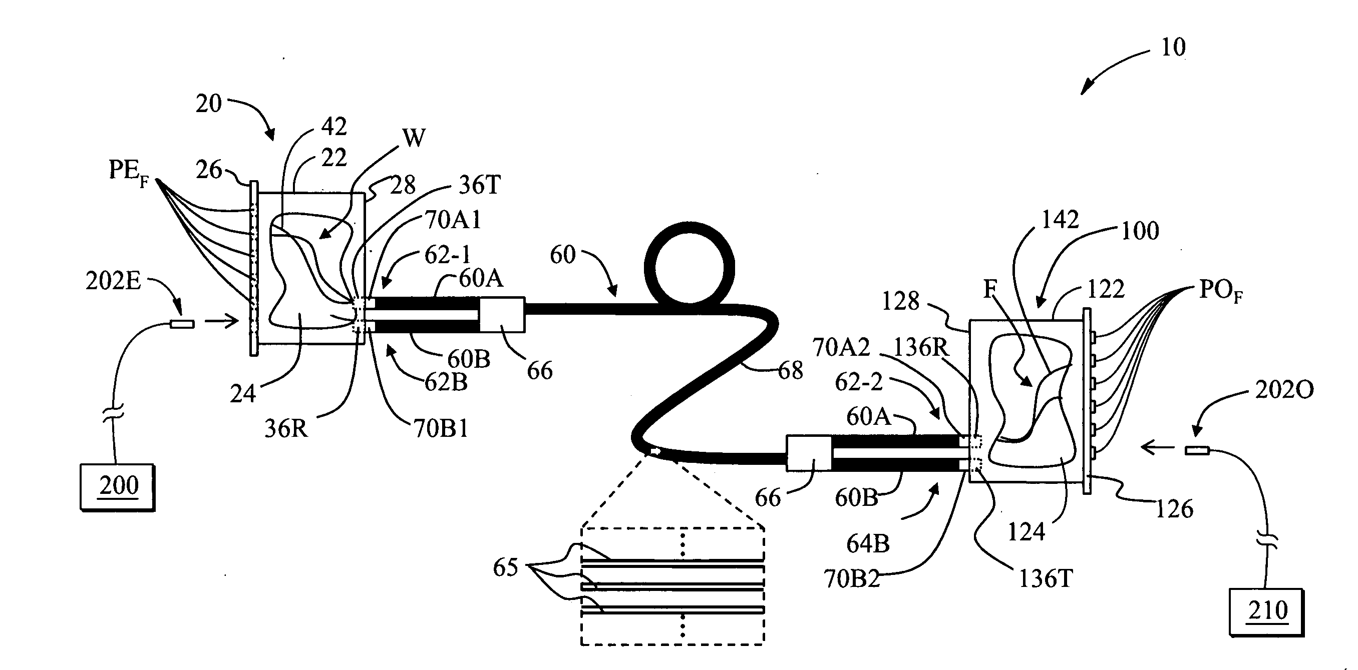
[0033]Reference is now made in detail to the present preferred embodiments of the invention, examples of which are illustrated in the accompanying drawings. Whenever possible, like or similar reference numerals are used throughout the drawings to refer to like or similar parts. It should be understood that the embodiments disclosed herein are merely examples, each incorporating certain benefits of the present invention. Various modifications and alterations may be made to the following examples within the scope of the present invention, and aspects of the different examples may be mixed in different ways to achieve yet further examples. Accordingly, the true scope of the invention is to be understood from the entirety of the present disclosure, in view of but not limited to the embodiments described herein.

[0034]In the discussion below and in the claims, the notation[0035]{a1,b1,c1 . . . }{a2,b2,c2 . . . }

denotes connecting a1 to a2, b1 to b2, c1 to c2, etc. Likewise, the notation[0...


PUM


Abstract

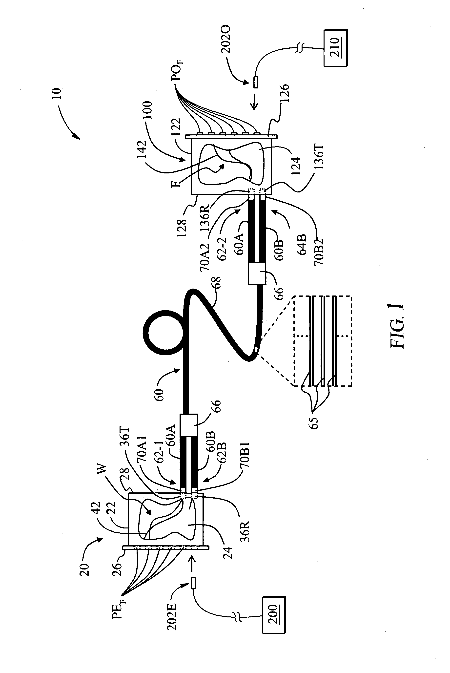
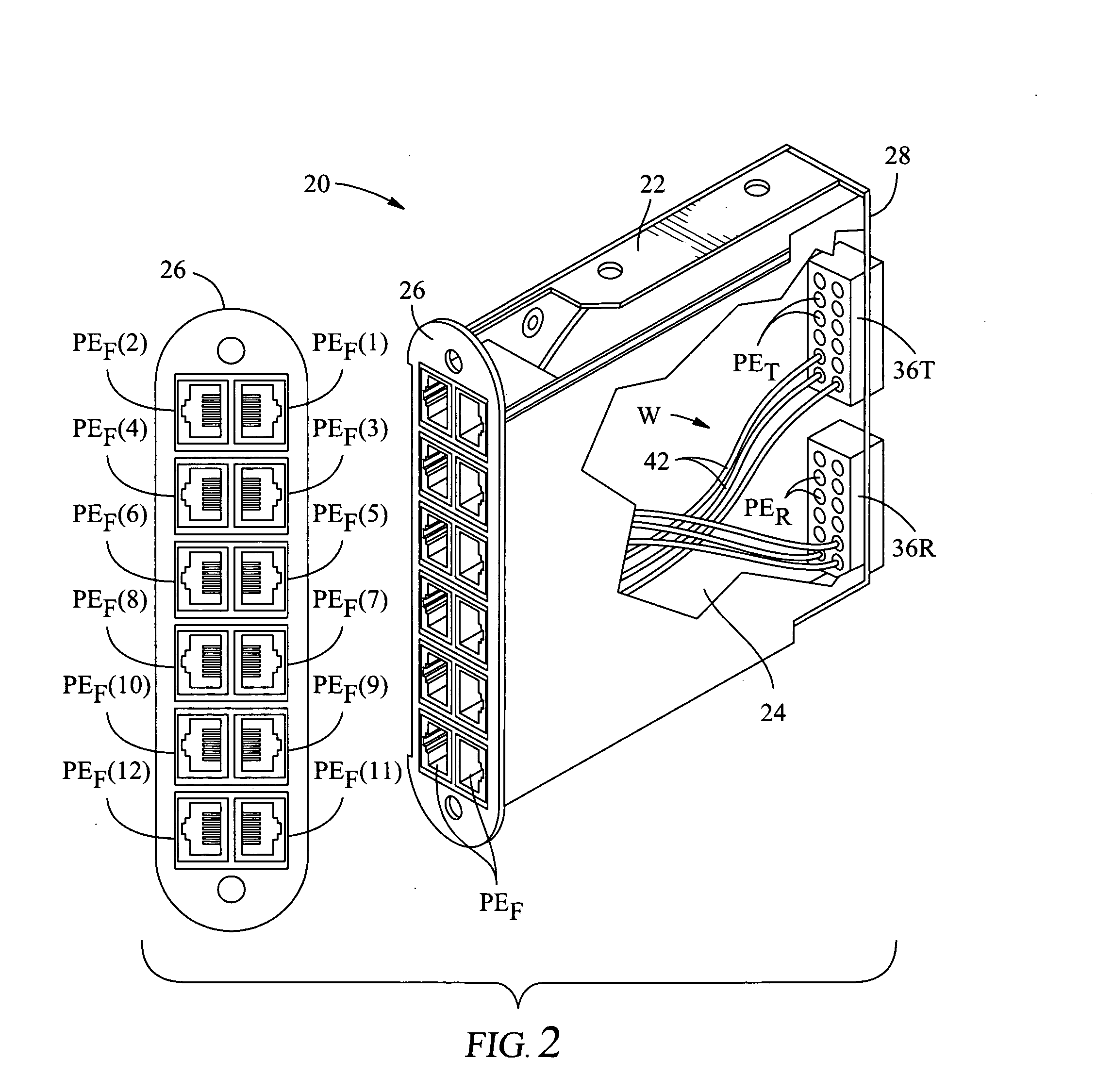
An optical interconnection module (100) for connecting to a media converter module (20) as part of a hybrid electrical-optical network (10) is disclosed. The optical interconnection module includes a transmitter connector (136T) having transmit ports (POT(i)) and a receiver connector having receive ports (POR(i)). The optical interconnection module also has transmit / receive ports (POF(i)) that are optically connected via a set (F) of fibers (142) to the transmit and receive ports of the transmitter and receiver connectors using one of two port configurations. Hybrid electrical-optical networks that utilize a trunk cable (60) to connect the media converter module to the optical interconnection module are also disclosed.

Description

FIELD OF THE INVENTION[0001]The present invention relates to optical fiber networks, and in particular relates to optical interconnection modules for use in hybrid electrical-optical networks that include media converter modules.BACKGROUND OF THE INVENTION[0002]Conventional computer networking in a telecommunication data center utilizes system equipment in the form of servers, switches and storage devices interconnected through a cabling infrastructure. Various types of cables, such as unshielded twisted pair (UTP), coaxial, and fiber optic, are used to interconnect the system equipment. These different types of cables can be used within the same type of network. For example, Ethernet networks or local area networks (LANs), can use many different types of cables, ranging from UTP to coaxial to fiber optic cables.[0003]The type of cable utilized in a given telecommunications network is dictated by the network interface card of the system equipment. For example, if the network interfa...

Claims


Application Information

Patent Timeline
IPC IPC(8): H04B10/00G02B6/38
CPCG02B6/4453G02B6/4452G02B6/44528
Inventor BARNES, RAY S.DENNIS, ROBERT W.UGOLINI, ALAN W.
Owner CORNING OPTICAL COMM LLC
Learn More