
Automatic slack adjuster tool

a technology of automatic slack adjustment and tool, which is applied in the direction of wrenches, screwdrivers, brake elements, etc., can solve the problems of yaw or roll of vehicles, difficulty in locating the cap b>140/b> with a screw driver, and failure of braking

Inactive Publication Date: 2010-04-29
THOMPSON BARRY
View PDF10 Cites 5 Cited by
  • Summary
  • Abstract
  • Description
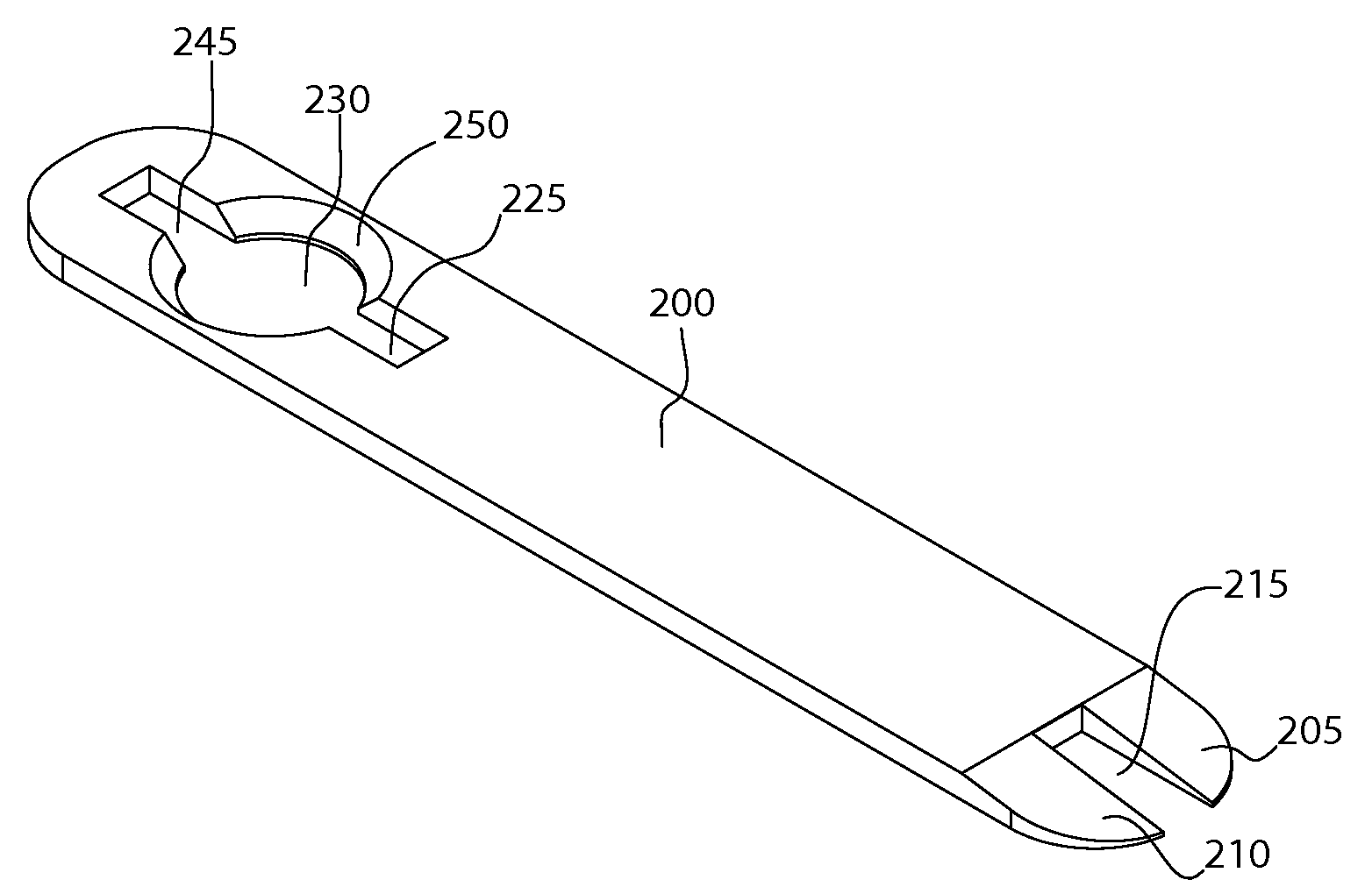
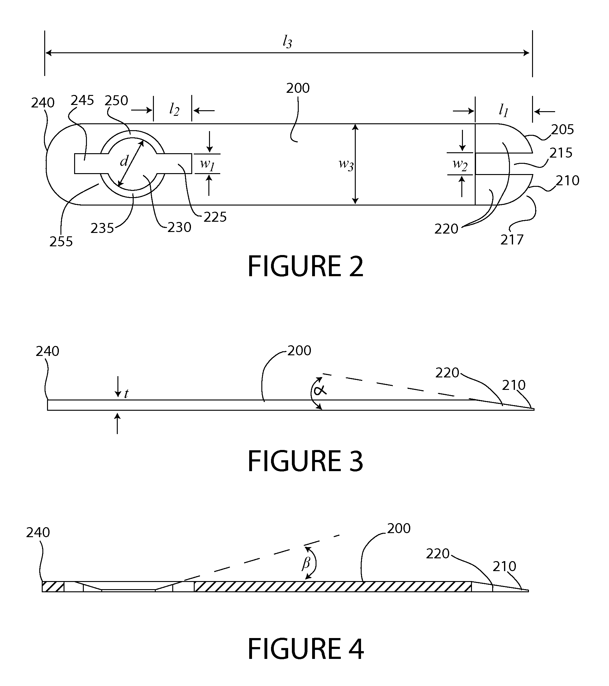
  • Claims
  • Application Information

AI Technical Summary

Benefits of technology

[0009]A slotted aperture is formed at the first end. The slotted aperture includes a hole formed through the tool. The hole has a diameter that is greater than the first diameter of the pawl cap of the pawl assembly of the slack adjuster. A first slot extends from the hole and has a width that is greater than the second diameter of the pawl shaft of the pawl assembly of the slack adjuster. A portion of the tool defining the hole includes a chamfered periphery. The chamfered periphery defining an inclined plane leading to the first slot. The inclined plane has a thickness that increases up to a thickness equal to a disengagement thickness. The disengagement thickness is effective to cause disengagement of the pawl assembly. The angle of the inclined plane relative to the longitudinal axis of the tool is less than 60 degrees, and preferably less than 30 degrees. The inclined planar surface providing a gradual transition to the disengagement thickness.

Problems solved by technology

Failure to maintain slack within acceptable limits may result in braking failure, such as an inability to stop, increased braking distance, or uneven braking forces causing the vehicle to yaw or roll.
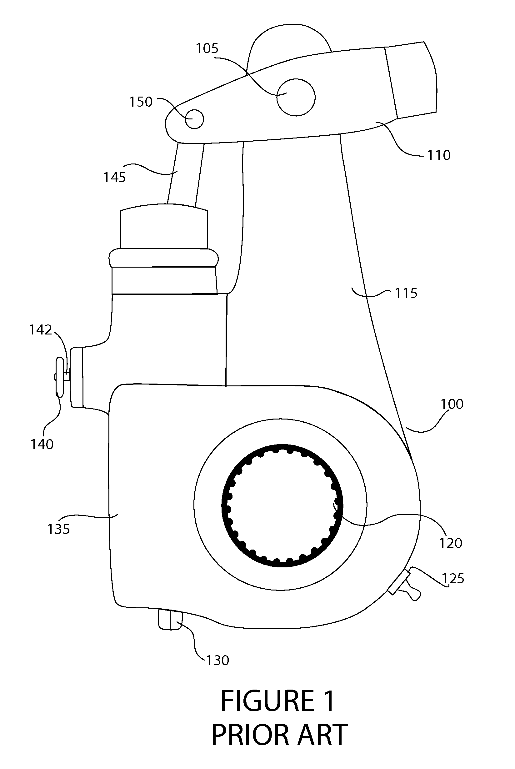
Unfortunately, however, locating the cap 140 with a screw driver can be difficult.

Method used


Image

  • Automatic slack adjuster tool
  • Automatic slack adjuster tool
  • Automatic slack adjuster tool

Examples


Embodiment Construction

[0024]Referring to the Figures, in which like parts are indicated with the same reference numerals, various views of an exemplary slack adjuster according to principles of the invention are shown. Generally, the tool 200 includes an elongated member in the form of a depressor having a proximal closed end portion 240 and a distal forked end portion 205, identified in FIGS. 2 through 6. The tool 200 may be composed of steel, aluminum, alloys thereof or other metallic or non-metallic materials suitable for hand tool construction for example, similar to the blade of a typical screwdriver or chisel. The thickness may vary significantly without departing from the inventive concepts described herein, so long as the working ends that engage the pawl assembly of a slack adjuster are not too thick to wedge fit between the slack adjuster pawl cap 140 and body 135 of a slack adjuster 100 and are thick enough (e.g., about ⅛ inch, plus or minus 10 to 20 percent) to cause disengagement of the pawl...


PUM


Abstract

A pawl disengagement tool intended for use with a slack adjuster has an elongated handle with a first end and an opposite second end, and a longitudinal axis extending from the first end to the second end. A slotted aperture formed at the first end includes a hole with a diameter that is greater than the first diameter of the pawl cap. A first slot extends from the hole and has a width that is greater than the second diameter of the pawl shaft of the pawl assembly of the slack adjuster. A portion of the tool defining the hole includes a chamfered periphery. The chamfered periphery defines an inclined plane leading to the first slot. The inclined plane has a thickness that increases up to a thickness equal to a disengagement thickness. The disengagement thickness is effective to cause disengagement of the pawl assembly. The second end of the tool includes a forked end that includes a pair of parallel spaced apart wedge-shaped prongs. In use, the forked end or slotted aperture is manipulated (e.g., slid) to a position between the pawl cap and the body of the slack adjuster. Then the slot of the pawl disengagement means is advanced between the pawl cap and the body of the slack adjuster, until the shaft reaches the end of the slot and the tool can be advanced no further. Upon completing this step, the pawl has been disengaged and the adjustment head may be freely rotated.

Description

FIELD OF THE INVENTION[0001]This invention generally relates to brake adjusting tools, and more particularly, to a tool for disengaging the pawl of a slack adjuster of an air brake assembly.BACKGROUND[0002]For safety and to comply with state and federal regulations, truck drivers must regularly measure, adjust and set air brakes. In particular, slack should be checked frequently, definitely before a trip, to determine if pushrod travel is within safe-working limits. Slack adjustment entails adjusting the brakes to keep air chamber pushrod travel and brake shoe travel within tolerance to ensure the brakes are effective. Pushrod travel means the distance the pushrod extends from the air brake chamber when the brakes are applied. Brake shoes should be adjusted to move a predetermined distance before the brake pads impinge against the interior surface of a brake drum. This distance denotes the slack in the pivotal movement of the slack adjuster. Failure to maintain slack within acceptab...

Claims


Application Information

Patent Timeline
IPC IPC(8): B25B13/02
CPCF16D65/0043B25B27/0035
Inventor THOMPSON, BARRY
Owner THOMPSON BARRY
Learn More