
Method and device for removing co2 and h2s

a technology of co2 and h2s, which is applied in the direction of liquid degasification, separation processes, gaseous fuels, etc., can solve the problems of increasing the amount of energy consumed for regenerating the rich solution, clogging of pipelines, corrosion of installations such as pipelines, etc., and achieves the reduction of the concentration of co2, the effect of reducing the pressure in the flash drum, and reducing the concentration of co2

Active Publication Date: 2010-04-29
MITSUBISHI POWER LTD
View PDF16 Cites 20 Cited by
  • Summary
  • Abstract
  • Description
  • Claims
  • Application Information

AI Technical Summary

Benefits of technology

[0011]In the above method, CO2 concentration and H2S concentration in the treated gas are measured. If the measured CO2 concentration or H2S concentration in the treated gas exceeds a predetermined concentration, an amount of the rich solution to be introduced from the flash drum into the stripper is increased and at the same time an amount of steam to be introduced into a reboiler in the stripper is increased to thereby heighten a rate of the rich solution having been regenerated. Otherwise, the releasing of CO2 and H2S from the rich solution is accelerated by reducing the pressure in the flash drum to thereby lower the concentration of CO2 and H2S in the rich solution.
[0012]According to the present invention, an installation for removing CO2 and H2S from the feed gas, such as natural gas and coal seam gas, by contacting the feed gas with rich solution, can reduce an amount of the rich solution to be circulated and, at the same time, can also reduce the regeneration energy for the rich solution.

Problems solved by technology

CO2 and H2S have to be removed before liquefaction because CO2 solidifies in the process of liquefaction and causes clogging of pipelines and a heat exchanger and H2S induces corrosion of installations such as pipelines.
For this reason, in order to decrease the property change of the rich solution in association with absorption of CO2 having high concentration, an excess amount of rich solution has to be circulated, causing a problem that an amount of energy to be consumed for regenerating the rich solution is increased.
Unfortunately, this method has a disadvantage that a predetermined performance cannot be obtained at the time of absorption since the concentration of CO2 and H2S remaining in the regenerated rich solution is high.

Method used


Image

  • Method and device for removing co2 and h2s
  • Method and device for removing co2 and h2s
  • Method and device for removing co2 and h2s

Examples


first embodiment

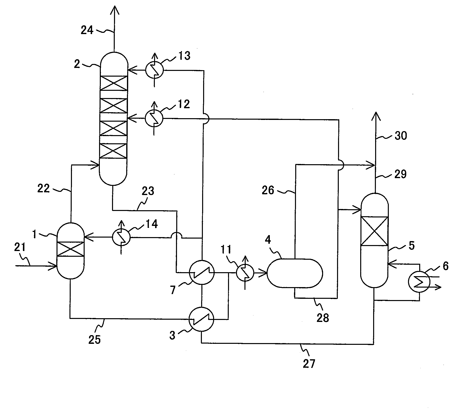
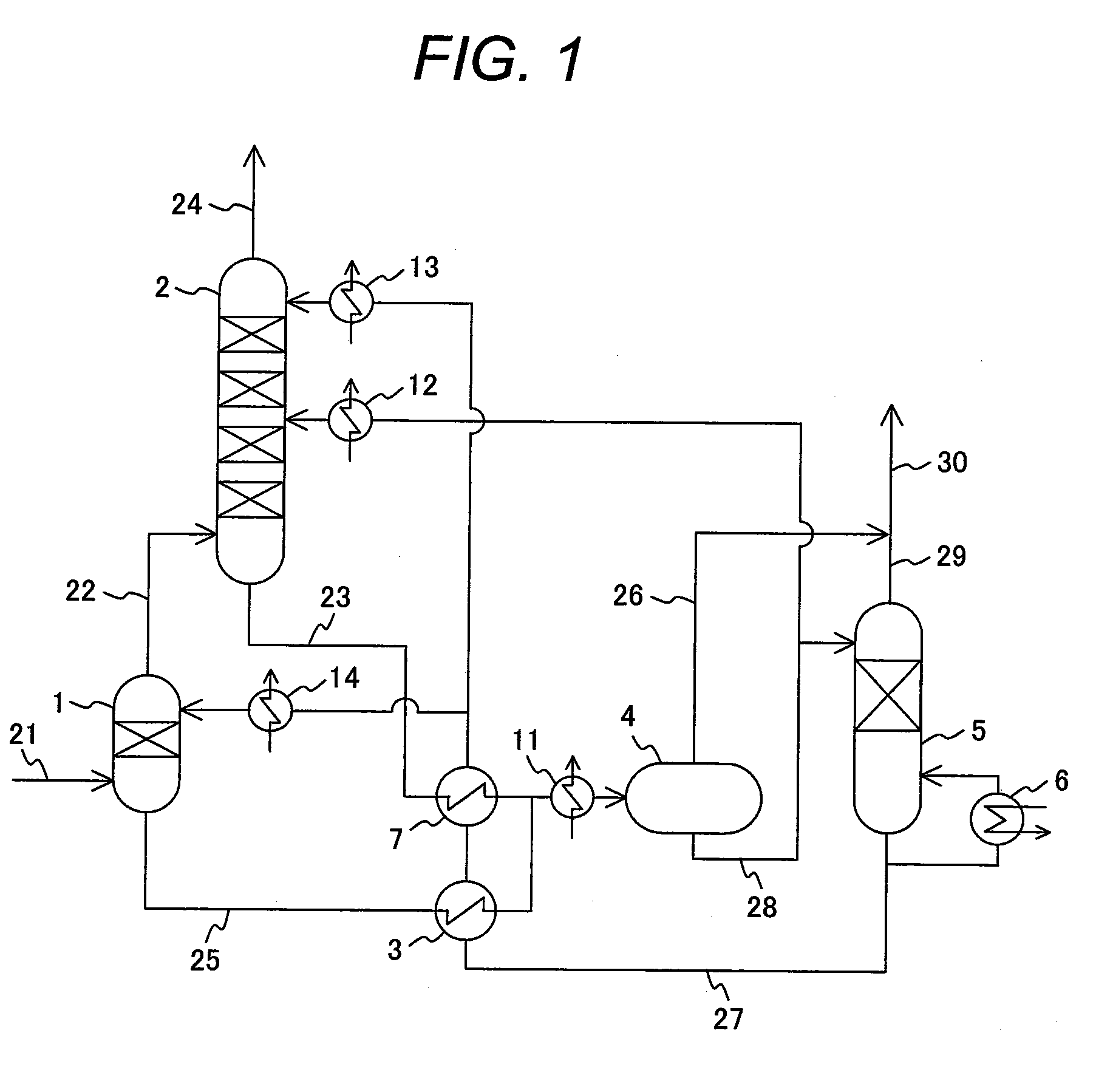
[0024]A first embodiment of the present invention will be explained with reference to FIG. 1. FIG. 1 is a block diagram of a device for removing acidic materials in the present embodiment. The present embodiment shows an example in which the present invention is applied to an installation for natural gas purification.

[0025]Natural gas 21 representing feed gas, to which necessary preprocessing and temperature adjustment have been effected beforehand, is supplied to a pre-absorber (first absorber) 1. The feed gas 21 is contacted in a manner of countercurrent with lean solution 27 supplied from a top of the pre-absorber 1, the acidic materials, such as CO2 and H2S, included in the feed gas 21 being absorbed there, and pre-treated gas 22 is exhausted from the top of the pre-absorber 1. On the other hand, rich solution 25 exhausted from a bottom is introduced into a lean / rich exchanger 3 and is heated through heat exchanging with the lean solution 27 introduced into the lean / rich exchang...

second embodiment

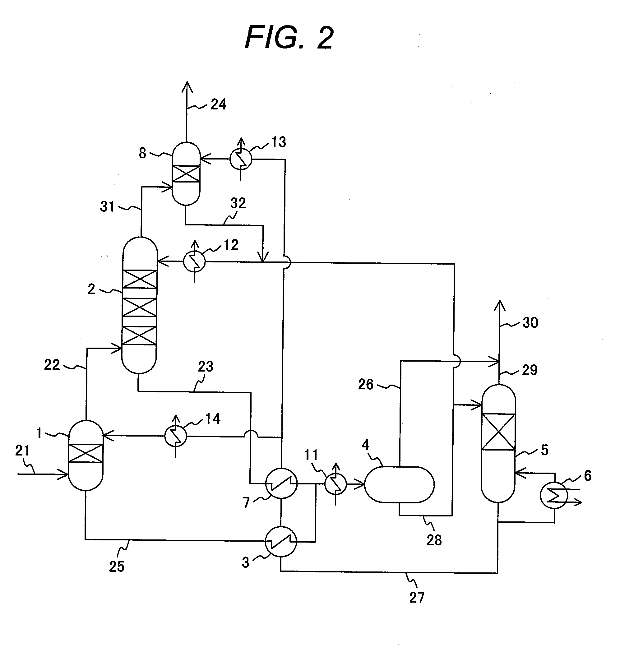
[0029]A second embodiment of the present invention will be explained with reference to FIG. 2. FIG. 2 is a block diagram of a device for removing acidic materials in the present embodiment. The present embodiment shows an example in which a secondary absorber (third absorber) 8 is added at a post stage of the absorber 2 in the first embodiment. Only different portions from the first embodiment will be explained.

[0030]The pre-treated gas 22, which is obtained after a part of CO2 and H2S included in the feed gas 21 is absorbed in the pre-absorber 1, is contacted in a manner of countercurrent with the semi-lean solution 28 supplied from the top portion of the absorber 2 in the filling portion of the absorber 2, thereby, a part of the acidic materials, such as CO2 and H2S, included in the pre-treated gas 22 is absorbed, and treated gas 31 is exhausted from the top portion. The treated gas 31 is contacted in countercurrent with the lean solution 27 supplied from the top portion of the se...

third embodiment

[0032]A third embodiment of the present invention will be explained with reference to FIG. 3. FIG. 3 is a block diagram of a device for removing acidic materials in the present embodiment. The present embodiment shows an example in which H2S included in the stripped gas 30 released from the rich solution in the flash drum and the stripper is removed by making use of an adsorbent and highly purified CO2 is recovered. Only different portions from the first embodiment will be explained.

[0033]After being cooled in a cooler 40, the stripped gas 30 including CO2 and H2S is introduced into a knock-out drum 41 where water 50 is removed and stripped gas 51 having lowered water concentration is obtained. The stripped gas 51 is introduced through a valve 62 to a catalytic adsorber 46. In the catalytic adsorber 46, an adsorbent is filled having features to adsorb H2S at a low temperature of 100 to 300° C., and thereafter, to convert the adsorbed sulfur into sulfur dioxide when gas including oxy...


PUM

PropertyMeasurementUnit
temperatureaaaaaaaaaa

Abstract

A method and a device for removing acidic materials, such as CO2 and H2S, with limited energy consumption are provided. The method comprises a step of introducing the feed gas into a first absorber, and removing CO2 and H2S from the feed gas by contacting the feed gas with a lean solution in the first absorber; and a step of introducing the feed gas into a second absorber, and removing CO2 and H2S remaining in the feed gas by contacting the feed gas with a semi-lean solution in the second absorber. The rich solution having absorbed CO2 and H2S in the first and second absorber is introduced into a flash drum where an internal pressure is kept lower than that in the first absorber and in the second absorber. After a part of CO2 and H2S is released from the rich solution in the flash drum to obtain a semi-lean solution, a part of the semi-lean solution is cooled and introduced into the second absorber to contact with the feed gas in the second absorber. A remaining part of the semi-lean solution is introduced into a stripper and heated to release remaining CO2 and H25 from the semi-lean solution and to obtain a lean solution. A part of the lean solution is cooled and introduced into the first absorber to contact with the feed gas in the first absorber. A remaining part of the lean solution is cooled, introduced into the second absorber at an upper level of the second absorber, and is contacted with the feed gas in the second absorber, and thereby obtaining a treated gas.

Description

CLAIM OF PRIORITY[0001]The present application claims priority from Japanese Patent Application JP 2008-273292 filed on Oct. 23, 2008, the content of which is hereby incorporated by reference into this application.FIELD OF THE INVENTION[0002]The present invention relates to a method and a device for removing CO2 and H2S at the same time from a variety of fuel gases including CO2 and H2S.BACKGROUND OF THE INVENTION[0003]In order to suppress global warming, utilization of natural gas having less amount of CO2 generation while combusting compared with other fossil fuels is considered to increase from now on. Natural gas produced from strata includes acidic materials such as CO2 and H2S. CO2 and H2S have to be removed before liquefaction because CO2 solidifies in the process of liquefaction and causes clogging of pipelines and a heat exchanger and H2S induces corrosion of installations such as pipelines. Other than the natural gas, coal seam gas, gas gasified from heavy oil, and gas gas...

Claims


Application Information

Patent Timeline
Patent Type & Authority Applications(United States)
IPC IPC(8): B01D53/14B01D53/18C01B32/50
CPCB01D53/02Y02C10/06B01D53/1425B01D53/1462B01D2251/102B01D2253/112B01D2255/20707B01D2255/20769B01D2256/24B01D2257/302B01D2259/80C01B17/0408C01B17/167C10L3/10C10L3/102Y02C10/04B01D53/1406Y02C20/40Y02P20/151
Inventor AKIYAMA, TOMOKO
Owner MITSUBISHI POWER LTD
Learn More