
Fluid divider block suitable for use at high pressures

Active Publication Date: 2010-04-29
COMPRESSOR PROD INT
View PDF3 Cites 11 Cited by
  • Summary
  • Abstract
  • Description
  • Claims
  • Application Information

AI Technical Summary

Benefits of technology

[0012]An object of the invention is to provide a reliable divider block for use at high pressures.
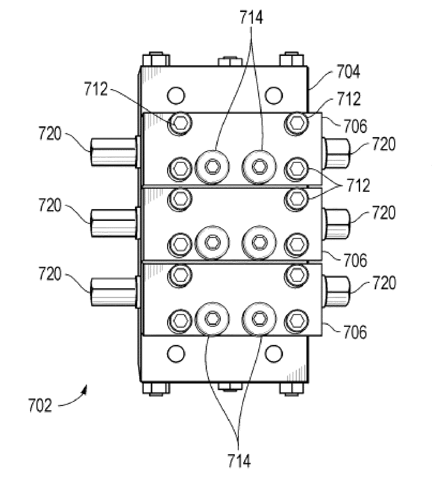
[0015]The invention comprises a divider block that resists substantial deformation at high fluid pressures. Various embodiments can include a stronger housing with thicker walls surrounding the bore; the use of additional bolts to connect the divider block section to the intermediate base plates to prevent distortion and to distribute torque evenly to ensure sealing of the o-rings; strengthening the base section by increasing its physical size, that is, using more metal to form the inlet, intermediate and end sections; and using larger heat-treated tie rod bolts to assemble the base section to decrease flexing and ensure sealing of all o-rings; and carefully tightening all bolts to their proper torque to prevent deformation, and providing for the connecting bolts counterbores that are sufficiently deep that the force from the tightened bolts does not deform the piston bores, even if the bolts are over tightened. Not all of the measures are required for every application.

Problems solved by technology

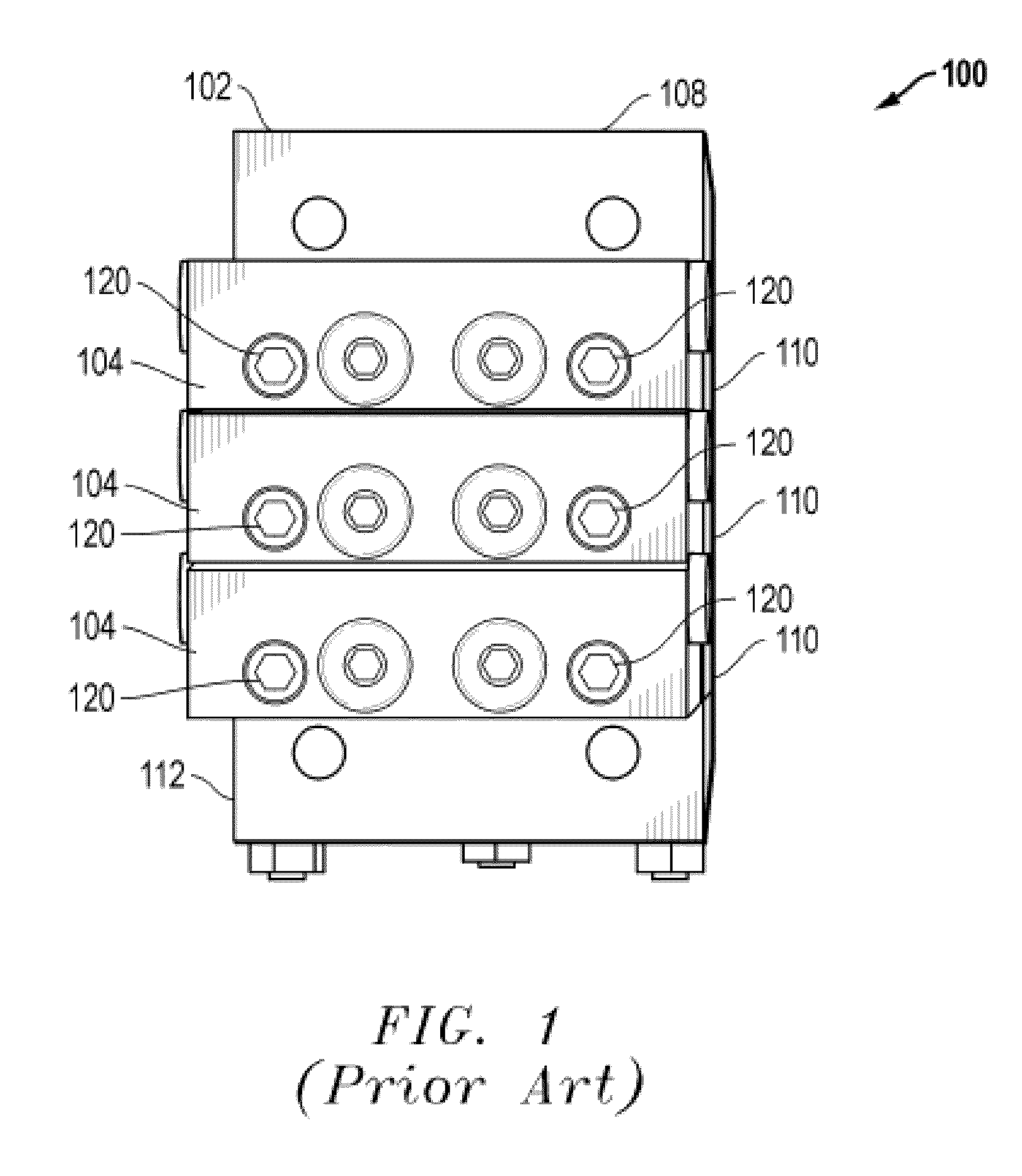
Applicant has found that at high pressures, conventional divider blocks deform and may not accurately dispense the required volume of fluid.
Applicant has found that with increased pressure, piston bores deform, and the pistons can fail to deliver the expected quantity of fluid, causing equipment failure or excess wear because of insufficient lubrication.
Deformation of the bore can also cause the piston to chafe against a side of the bore, thereby causing premature wear of the piston.
Because this problem was not recognized, divider blocks have not been designed to resist deformation.

Method used


Image

  • Fluid divider block suitable for use at high pressures
  • Fluid divider block suitable for use at high pressures
  • Fluid divider block suitable for use at high pressures

Examples


Embodiment Construction

[0033]To investigate the problem of compressor failures when the divider block providing lubrication to the compressor appears to be cycling normally, applicant built a test stand to measure the volumes of fluid dispensed from several commercially available divider blocks at various pressures. Applicant monitored the number of cycles and the nominal output volume at working pressures of up to about 5000 psi using proflo® monitors described in U.S. Pat. No. 5,835,372 and commercially available from CC Technology, Midland, Tex., the assignee of the present application. The proflo® monitor measures the number of cycles of a divider block and can report and trend the output volume of the divider blocks at each outlet point while the system is operating at actual operating pressures. Applicant also measured the actual volume of fluid dispensed into an outlet path of the divider, using a single inlet, single outlet divider block located in the fluid outlet path downstream of the divider b...


PUM

PropertyMeasurementUnit
Fractionaaaaaaaaaa
Fractionaaaaaaaaaa
Fractionaaaaaaaaaa

Abstract

The invention is a divider block assembly suitable for use at high fluid pressures. Applicant has found that a sufficiently deep counterbored hole allows a mounting bolt to apply the sealing pressure well below the divider block surface, which can reduce or eliminate the compressive force on the metal around the piston bore, thereby reducing or eliminating distortion of the piston bore of the divider block and providing.

Description

[0001]This application is a continuation-in-part application of U.S. application Ser. No. 11 / 405,383, filed on Apr. 17, 2006, which is a continuation application of U.S. application Ser. No. 10 / 816,212, filed on Apr. 1, 2004 and now U.S. Pat. No. 7,096,889, which claims priority from U.S. Provisional Application No. 60 / 459,403, filed on Apr. 1, 2003, all of which are hereby incorporated by reference.TECHNICAL FIELD OF THE INVENTION [0002]The present invention relates to high pressure, low volume fluid flow systems.BACKGROUND OF THE INVENTION[0003]Without adequate lubrication, industrial tools and machines such as compressors can be seriously damaged or destroyed. In many applications, a pump pressurizes a lubricant which is then distributed to multiple lubrication points using a device referred to as a “divider block” or “divider valve.” In a divider block, the pressurized lubricant causes a set of pistons to move back and force in within piston bores, the moving pistons opening and...

Claims


Application Information

Patent Timeline
IPC IPC(8): F16K11/10B23P11/00
CPCY10T29/49947F16K11/07F16K27/003F16N25/02F16N25/00Y10T137/87885
Inventor ROYS, CURTIS
Owner COMPRESSOR PROD INT
Learn More