Using An Acoustic Ping and Sonic Velocity to Control an Artificial Lift Device

a technology of artificial lift and acoustic ping, applied in the direction of instruments, surveying, borehole/well accessories, etc., can solve the problems of foam accumulation on the well fluid surface, unstable pressure measurement, and another source of error

Active Publication Date: 2010-04-29
BAKER HUGHES INC
View PDF16 Cites 18 Cited by
  • Summary
  • Abstract
  • Description
  • Claims
  • Application Information

AI Technical Summary

Problems solved by technology

The T-wave, or tube wave, is the reflection from the top of the fluid or bottom of the well and is generally considered interference in well logging.
For example, pressure measurements can be unstable at the high temperatures of a well-bore environment.
In addition, foam that accumulates on the well fluid surface provides another source of error.

Method used


Image

  • Using An Acoustic Ping and Sonic Velocity to Control an Artificial Lift Device
  • Using An Acoustic Ping and Sonic Velocity to Control an Artificial Lift Device
  • Using An Acoustic Ping and Sonic Velocity to Control an Artificial Lift Device

Examples


Embodiment Construction

[0023]The present invention will now be described more fully hereinafter with reference to the accompanying drawings in which embodiments of the invention are shown. This invention may, however, be embodied in many different forms and should not be construed as limited to the illustrated embodiments set forth herein; rather, these embodiments are provided so that this disclosure will be thorough and complete, and will fully convey the scope of the invention to those skilled in the art. Like numbers refer to like elements throughout.

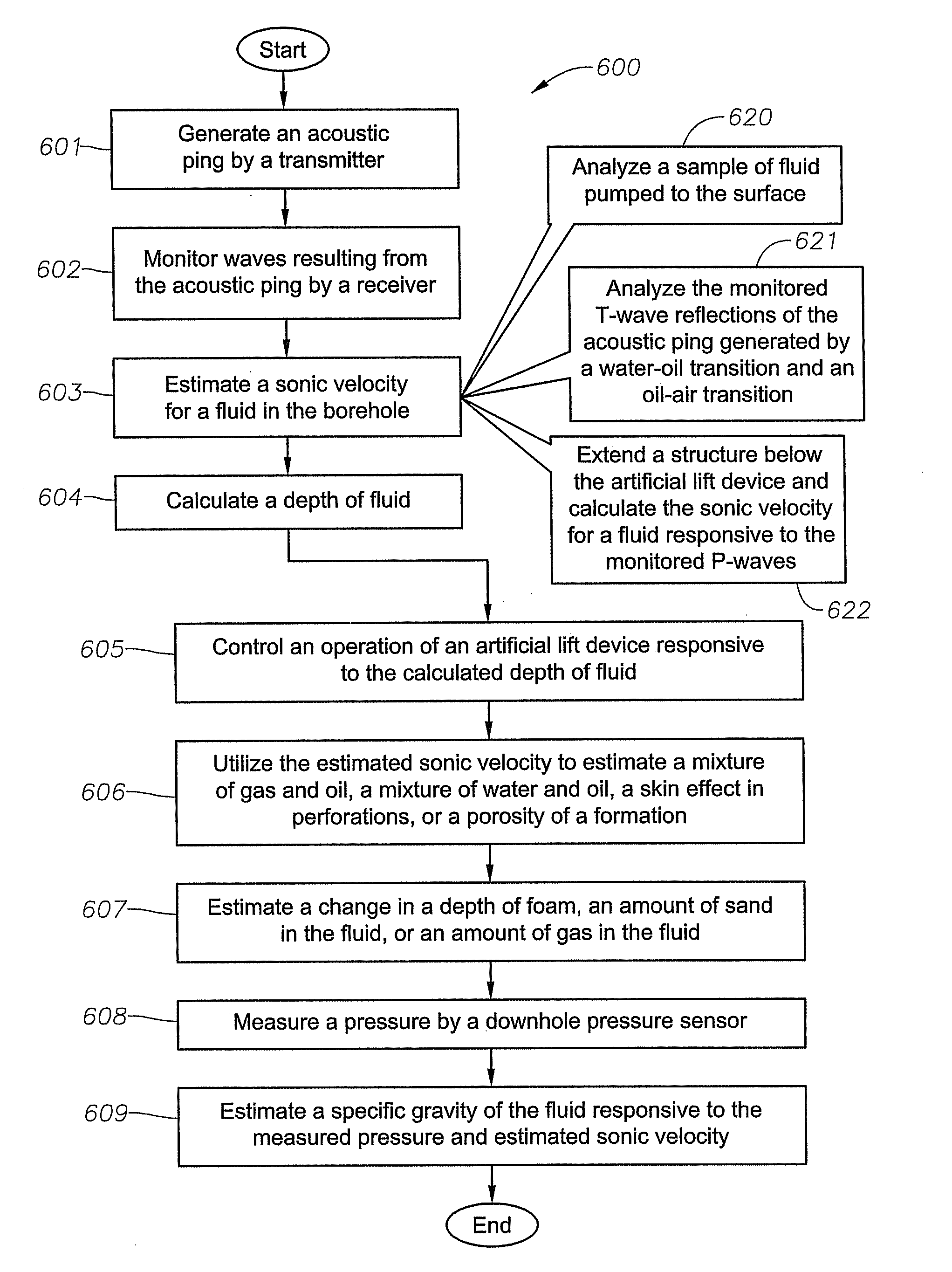
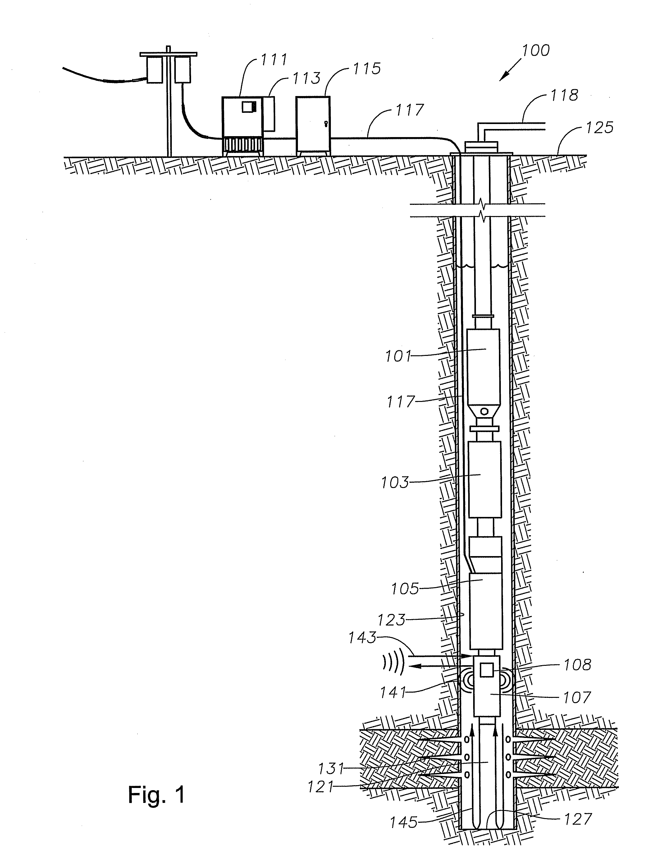
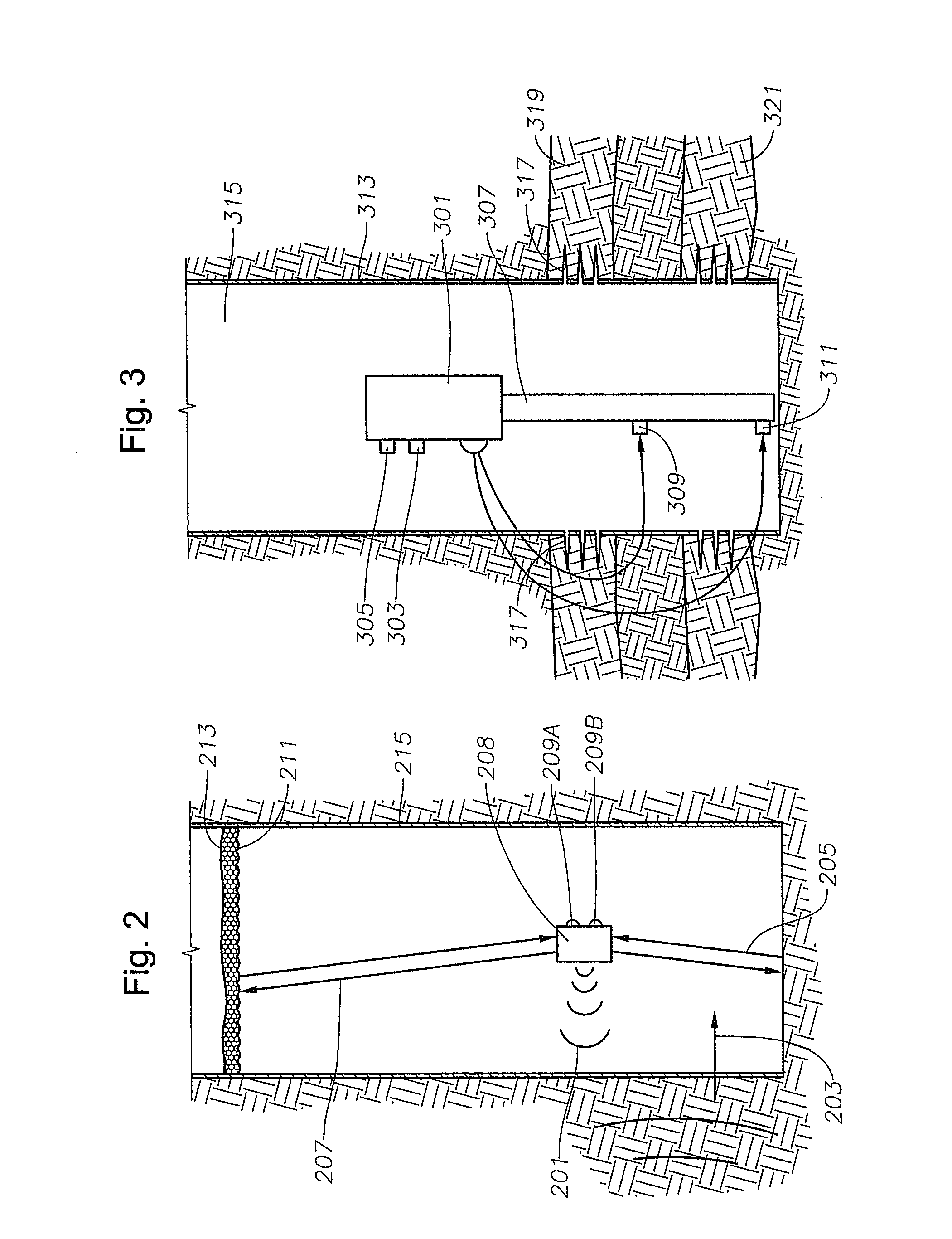
[0024]An example embodiment provides a transducer, for example, a ceramic quartz, near the bottom of an artificial lift device, such as, an electrical submersible pump assembly, within a borehole. In one embodiment, the transducer is utilized as both a transmitter and receiver. The transducer is excited to oscillation, or “pinged,” by a high voltage signal. The transducer transforms the high voltage signal into sound energy, generating an acoustic ping. T...


PUM


Abstract

A transmitter generates an acoustic ping in a fluid in a borehole, and a receiver monitors waves resulting from the acoustic ping. Responsive to the monitored waves, an attribute of the fluid is estimated, including a sonic velocity, a mixture of gas and oil, a mixture of water and oil, an amount of sand, an amount of gas, an amount of skin effect, or a depth of fluid. An operation of the artificial lift device is then controlled responsive to the estimated attribute. Alternately, a sonic velocity is estimated for the fluid through an analysis of a sample pumped to the surface or through an analysis of monitored waves. A depth of the fluid is calculated responsive to the estimated sonic velocity for the fluid in the borehole and the monitored T-waves. The operation of the artificial lift device is then controlled responsive to the calculated depth of fluid.

Description

BACKGROUND[0001]1. Field of the Invention[0002]This invention relates in general to artificial lift devices and, in particular, to controlling an operation of an artificial lift device by monitoring waves resulting from an acoustic ping.[0003]2. Description of the Prior Art[0004]It is known in sonar and well logging technology to utilize an acoustic ping to estimate a distance to an object or a sonic velocity of a material. An acoustic ping is a pulse of sound, which is generated by a transmitter, is propagated as a wave through a medium, is typically reflected off an object or a change in propagation media, and then is collected by a receiver for analysis. An acoustic ping can also refer to a series of pulses. The sonic velocity of a material is the speed in which sound travels through the material (including sound having sonic, ultrasonic, or subsonic frequencies). The sonic velocity of a material can also be known as the velocity and as the ultrasonic velocity; it is affected by ...

Claims


Application Information

Patent Timeline
Patent Type & Authority Applications(United States)
IPC IPC(8): E21B47/04E21B47/14E21B47/06E21B43/00
CPCE21B43/121E21B47/101G01V1/44E21B47/18E21B47/14E21B43/128E21B47/107
Inventor MCCOY, ROBERT H.CAMPBELL, DUSTIN B.
Owner BAKER HUGHES INC
Why Eureka
Try Eureka