Intra-ventricular cardiac assist device and related method of use

a technology of cardiac assist device and aortic valve, which is applied in the direction of circulatory assistance device, heart stimulator, therapy, etc., can solve the problems of unpredicted damage, reduced cardiac output, and energy exerted, so as to reduce the load on the left ventricle, increase blood flow, and reduce the effect of energy consumption

Inactive Publication Date: 2007-12-13
OVIL YOEL +2
View PDF9 Cites 34 Cited by
  • Summary
  • Abstract
  • Description
  • Claims
  • Application Information

AI Technical Summary

Benefits of technology

[0005] Advantage of the present invention device and related method and system is in the provision of a specifically shaped device that is inflated within the ventricle at the end of the slow ejection phase of the beating heart. This phase corresponds to the ascending part of the ECG-T wave of the heart. Therefore the energy exerted by the balloon is not contradicting the natural muscle power of the beating heart but only displacing the residual volume of blood and fluid (which are the direct consequence of heart failure) at the end of the muscle contraction. Further more, the balloon is not obstructing the normal ejecting phase of the heart as it does when inflated in early systolic phase as described in the Choy et al. devices.
[0006] Use of an intra-aortic balloon reduces the load on the left ventricle and raises aortic pressure to increase the blood flow to the coronary and carotid arteries. This can reduce the pulmonary capillary wedge pressure by approximately 20%, and can decrease aortic systolic pressure by 10% to 20%. Mean arterial pressure can increase by 30 to 40% secondary to enhanced diastolic blood pressure, and both cardiac output and stroke volume may experience a moderate increase.
[0007] An intra-aortic balloon may be indicated for several conditions, such as cardiogenic shock; as an adjunct to thrombolysis or percutaneous transluminal coronary angioplasty (PTCA) in acute myocardial infarction (AMI) to maintain vessel patency; prior to coronary artery bypass graft surgery in high risk patients; severe mitral regurgitation (mitral valve too loose); decompensated mitral stenosis (mitral valve too tight); as a bridge to transplant (if an organ is readily available); refractory congestive heart failure; mechanical complication of AMI, i.e., mitral regurgitation due to papillary involvement or ventricular septal defect; or unstable angina refractory to medical therapy.
[0008] The present invention provides an intra-ventricular cardiac-assist system. The system of the invention includes a sl

Problems solved by technology

The Choy patents define a balloon which is inflated at the very early stages of the systolic phase and as a consequence the energy exerted is destructive.
The heart muscle and the balloon are working in opposite di

Method used


Image

  • Intra-ventricular cardiac assist device and related method of use
  • Intra-ventricular cardiac assist device and related method of use
  • Intra-ventricular cardiac assist device and related method of use

Examples


Embodiment Construction

[0028] In order to understand the invention and to see how it may be carried out in practice, a preferred embodiment will now be described, by way of non-limiting example only, with reference to the drawings.

[0029] As used in the specification herein the terms intra-ventricular device and intra-ventricular balloon are used interchangeably and are meant to have the same meaning unless otherwise stated.

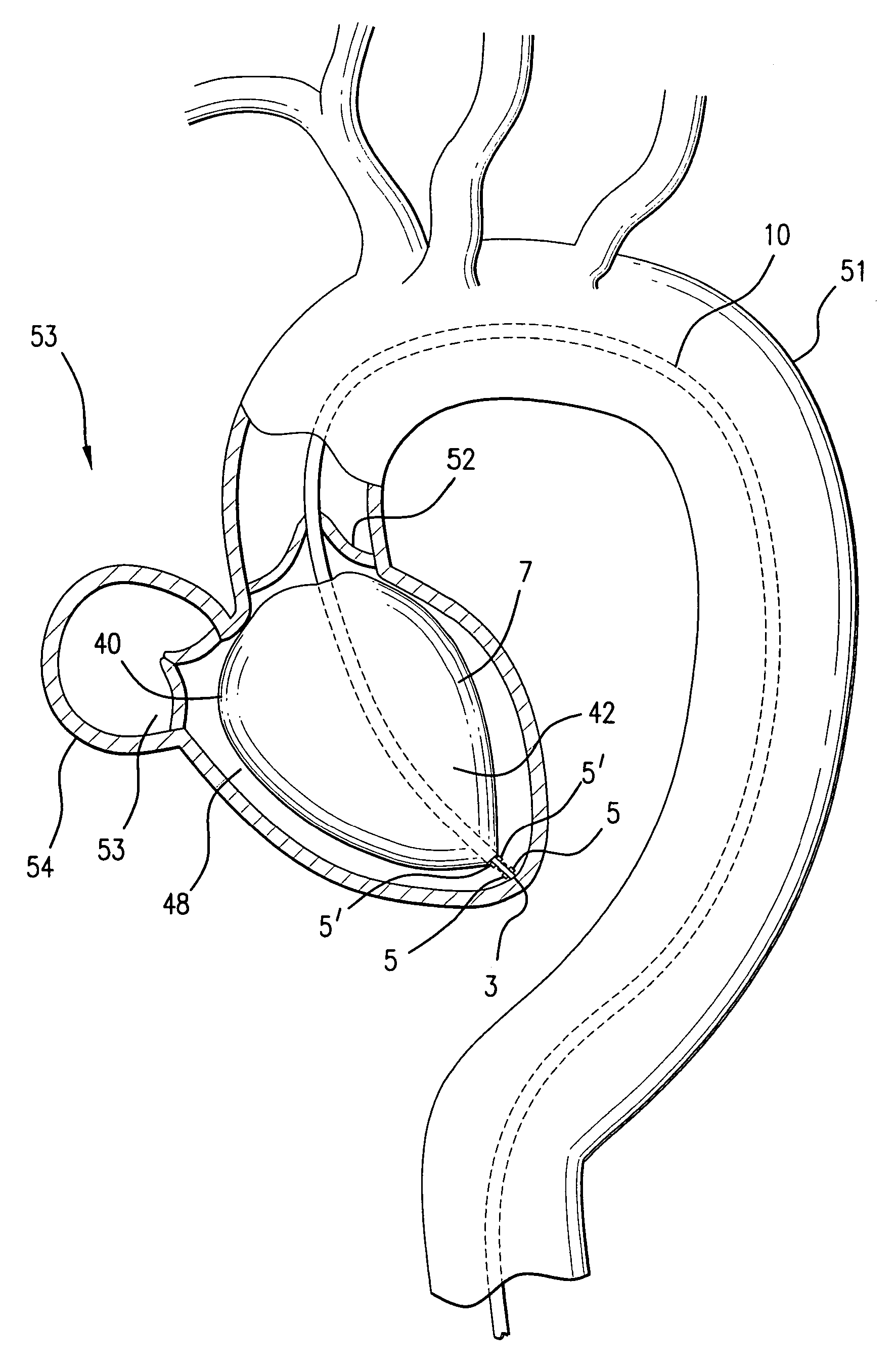
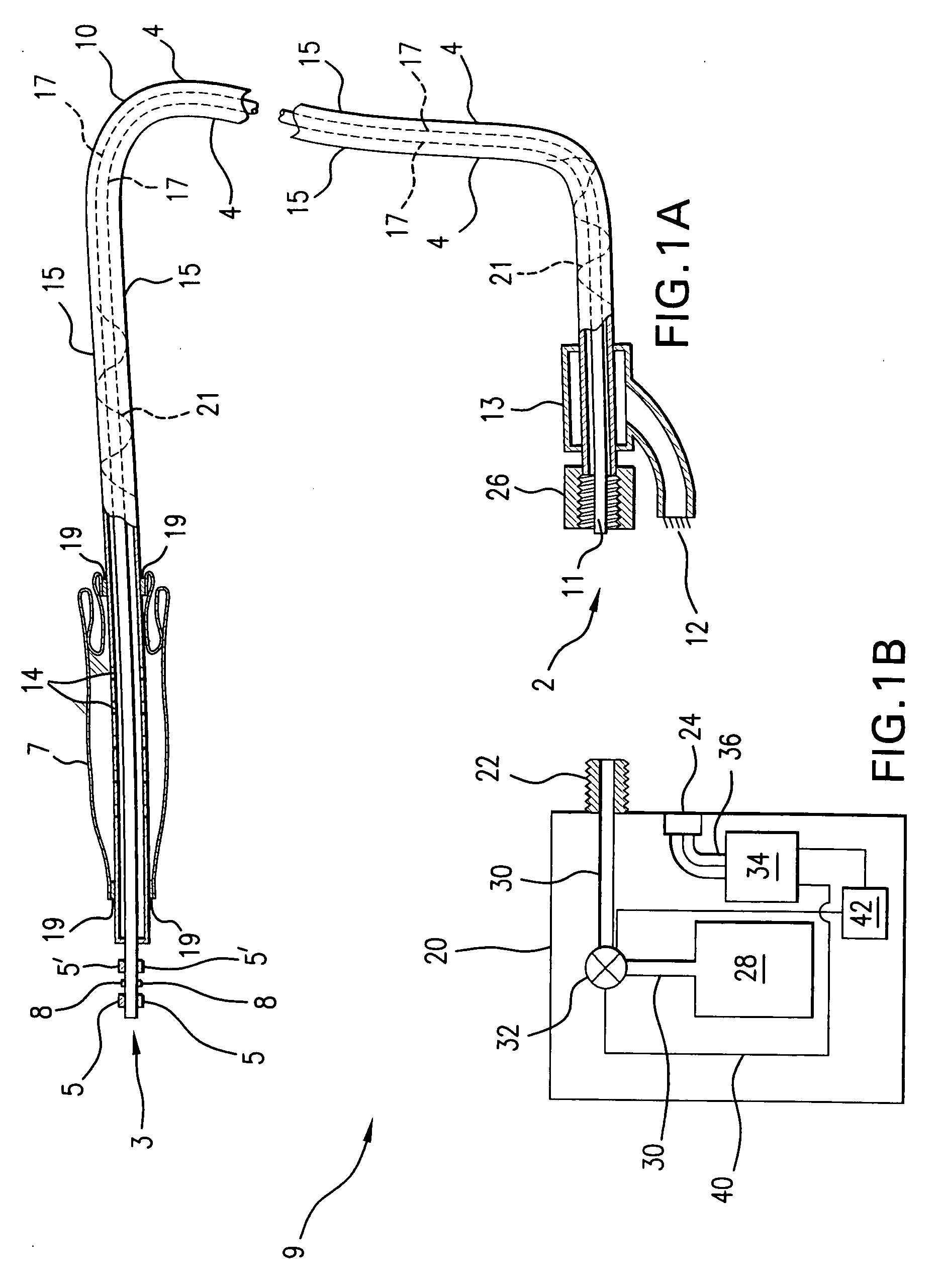
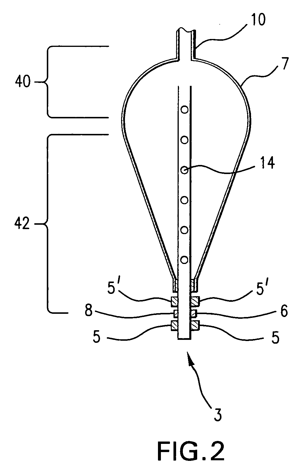
[0030]FIG. 1A shows an intra-ventricular balloon and FIG. 1B the related system, generally indicated by 9, in accordance with one embodiment of the invention. The system 9 includes a slender flexible catheter 10 with a proximal end 2 and a distal end 3. An inflatable balloon 7, to be described in detail below, is mounted on the catheter 10 near the distal end 3. The balloon 7 is shown in FIG. 1A in its deflated state and compactly folded onto the outer surface of the catheter 10. The catheter has an outer tubular member 15 and an inner tubular member 17 coaxial with the outer tubular ...


PUM


Abstract

A system and method for cardiac assist of a heart. The system comprises a catheter on which is mounted an inflatable balloon configured for inflation inside a ventricle. The system preferably includes a fluid pump and a processor configured to activate the pump to inflate the intra-ventricular balloon in the ventricle during a predetermined first phase of the cardiac cycle and to deflate the balloon during a predetermined second phase of the cardiac cycle. The predetermined first phase may be the end of the slow ejection phase corresponding to the ascending part of the T wave, and the predetermined second phase may begin at the peak of systolic augmentation resulting from inflation of the balloon which corresponds to the descending part of the T-wave. The method of the invention includes delivering the balloon to a ventricle of the heart and transiently inflating the balloon to achieve a predetermined intra-ventricular systolic pressure

Description

[0001] This application claims the benefit of U.S. provisional application No. 60 / 794,091 filed Apr. 24, 2006, which is incorporated herein in its entirety by reference.FIELD OF THE INVENTION [0002] This invention relates to cardiac assist devices and their related method of use. More particularly, the cardiac assist device is cone-shape to provide minimal pressure on the ventricular wall and sub apparatus of the mitral value while permitting optimal ejection of blood into the ventricular outflow track. BACKGROUND OF THE INVENTION [0003] It is known in the art to provide cardiac assistance by introducing a balloon into the thoracic aorta of a patient and causing the balloon to inflate during diastole and deflate during systole. An extracorporeal pumping unit inflates and deflates the balloon in coordination with the electrocardiogram (ECG), with a suitable neutral drive gas, such as helium. Electrocardiograph leads provide timing information, such as the R wave, to identify systole ...

Claims


Application Information

Patent Timeline
IPC IPC(8): A61M1/12A61M60/139A61M60/17A61M60/295A61M60/497A61M60/515A61M60/531A61M60/554A61M60/843
CPCA61M1/1072A61M1/1074A61N1/362A61N1/056A61M60/274A61M60/17A61M60/531A61M60/554A61M60/497A61M60/139A61M60/515A61M60/295A61M60/843
Inventor OVIL, YOELOVIL, YOTAMOVIL, ACE
Owner OVIL YOEL
Why Eureka
Try Eureka