Vehicle having internal combustion engine and rotating electric machine as power supplies
a technology of rotating electric machines and internal combustion engines, which is applied in the direction of propulsion parts, electric propulsion mounting, transportation and packaging, etc., can solve the problems of degrading driving performance, increasing the weight of the vehicle body, and reducing the comfort of interior passengers, so as to prevent the center of gravity and minimize the effect of comfort degradation
- Summary
- Abstract
- Description
- Claims
- Application Information
AI Technical Summary
Benefits of technology
Problems solved by technology
Method used
Image

Examples
first embodiment
Modification of First Embodiment
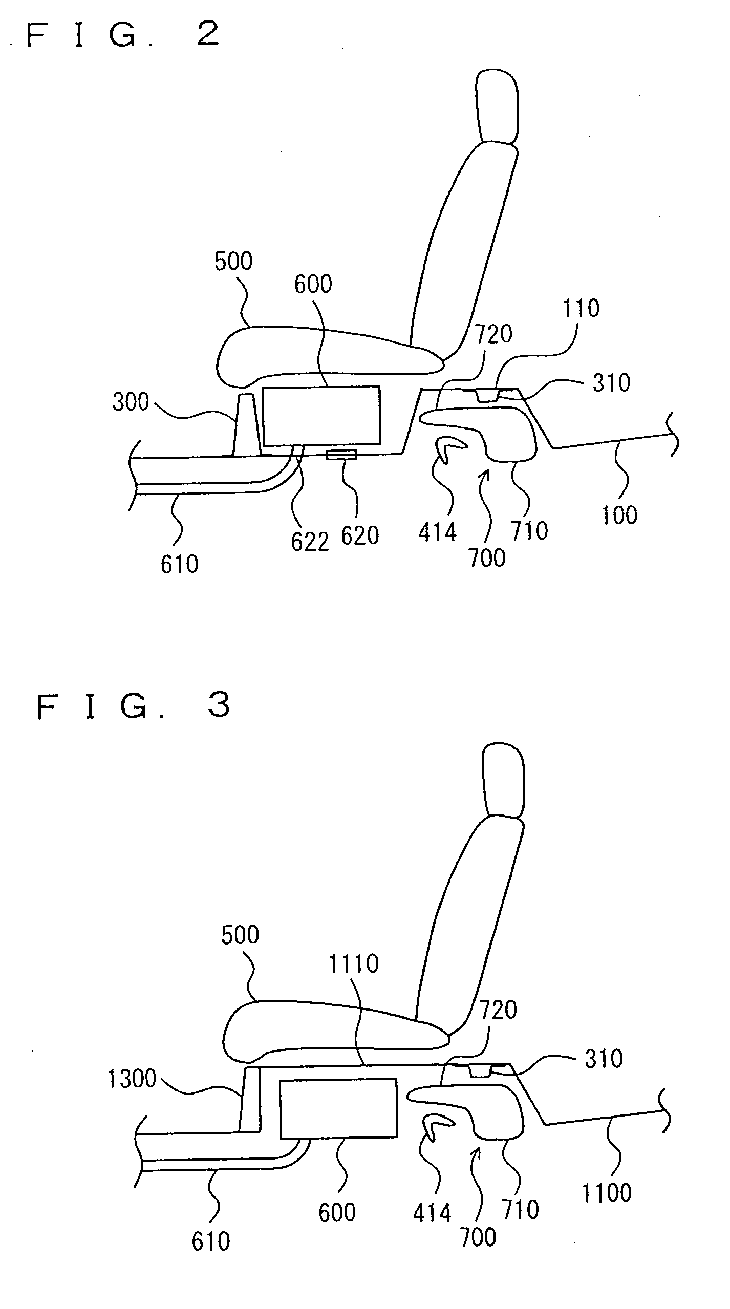
[0051]The structure of the vehicle according to the above-described first embodiment may be modified as described hereinbelow according to the present modification.
[0052]More specifically, rear floor panel 100 and first rear cross member 300 according to the above-described first embodiment are replaced with a rear floor panel 1100 and a first rear cross member 1300, as shown in FIG. 3.
[0053]Rear floor panel 1100 is formed with a raised portion 1110 raised upwardly from below rear seat 500 to the rear side. First rear cross member 1300 is connected to the front end face of raised portion 1110 disposed substantially vertically.
[0054]In the region located below raised portion 1110, battery pack 600 is disposed at the front side (i.e., below rear seat 500), while cross beam 414 and fuel tank 700 are disposed at the rear side.
[0055]As described above, in the region located below raised portion 1110, battery pack 600 is disposed at the front side where cro...
second embodiment
Modification of Second Embodiment
[0063]The structure of the vehicle according to the above-described second embodiment may be modified as described hereinbelow according to the present modification.
[0064]More specifically, rear floor panel 2100 and first rear cross member 300 according to the above-described second embodiment are replaced with rear floor panel 1100 and first rear cross member 1300 described in the modification of the first embodiment as shown in FIG. 5.
[0065]In the region located below raised portion 1110, battery pack 1600 is disposed at the front side, while fuel tank 1700 is disposed at the rear side.
[0066]As described above, in the region located below raised portion 1110, battery pack 1600 is disposed at the front side where stabilizer 420 is not disposed, while fuel tank 700 is disposed at the rear side where stabilizer 420 is disposed. Accordingly, similarly to the second embodiment, the mounting space for battery pack 1600 and fuel tank 1700 can be ensured w...
third embodiment
[0067]With reference to FIG. 6, a vehicle according to the present embodiment will now be described. The vehicle according to the present embodiment is different from that of the above-described first embodiment in that a battery pack 2600 and a junction box 800 are included additionally. The remaining structure is identical to that of the vehicle according to the above-described first embodiment. Like components are denoted by like reference characters, and function identically. Therefore, detailed description thereof will not be repeated here.
[0068]Battery pack 2600 is connected to the inverter mounted in the engine compartment in parallel with battery pack 600. Battery pack 2600 may alternatively be connected in series to battery pack 600. Battery pack 2600 may be a large-capacitance capacitor. Battery pack 2600 is disposed on the top face of raised portion 110.
[0069]Junction box 800 is disposed between the rear end of battery pack 600 and the front inclined surface of raised por...
PUM
 Abstract
Description
Claims
Application Information